In a perfect world we’d have full-size 160m Beverage antennas fanning out like the spokes of a wheel from a centrally located shack, and the feedpoints would all be located near the shack. Most of us don’t have the necessary 80 acres of land so the feedpoints to our Beverages often end up far away and must be fed through long runs of coaxial cable.
For example, let’s say I want to install a unidirectional Beverage aimed northeast and the shack is located in the northeast corner of the property. The Beverage wire must extend 800 feet towards the southwest of the shack, the termination resistor must be located at the shack end and the feed is all the way at the southwest end. I have to run the 800 foot Beverage wire plus 800 feet of coax to bring the signal to the shack. You can’t do anything to change the geometry of this problem but I’ll show here how the coax can serve both as the feedline and the Beverage wire.
Sometimes we build reversible Beverage antennas that require long runs of coax plus distant relay boxes to perform the required switching. The coax is often buried, making it susceptible to physical damage, especially on farmland, and subject to contamination from constant exposure to moisture. Buried coax can be punctured by nearby lightning strikes. Locating the damage and making repairs can mean replacing the entire run of coax.
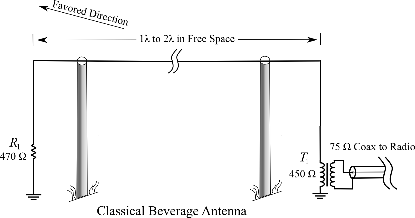
THE CLASSICAL BEVERAGE ANTENNA
EMBODIMENT ONE: The basic idea.
The basic design concept is shown in the following diagram. The additional embodiments below use the same technique described here. The coaxial cable is suspended above the ground and the outer skin of the coax shield serves as the “wire” of a classical Beverage antenna. The tiny currents induced in the antenna wire (the outer shield of the coax) are referenced to earth ground and are presented to the 450 ohm primary of matching transformer T-1, exactly as in the classical Beverage shown above. T-1’s secondary connects to the shield and center conductor of the coaxial cable feedline, which happens to be the same coax that forms the active element of the antenna. The RF signal injected by T-1 propagates inside the coax to the opposite end (the terminating resistor end) of the antenna. Note that T-1 is an isolation transformer with two independent windings.
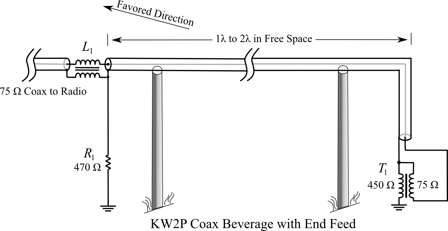
At the terminating resistor end of the antenna, we are faced with the problem of extracting the signal we want, which is propagating inside the coax, while preventing the RF currents traveling on the outer surface of the coax shield from flowing beyond this point. This is a common problem in antennas that is solved by means of a balun (L1). However the problem in this case is bigger than we usually face with ham antennas. In the case of a Beverage antenna we are likely working at 1.8 MHz, which means the inductances required are large. We are also working with an impedance that is 10 times higher than what we normally work with so the required inductances are that much higher still. (Remember that the balun is concerned with blocking the outside surface currents at the 500 ohm impedance of the Beverage. The 75 or 50 ohm internal impedance of the coax is irrelevant as far as the balun is concerned.)
The rule of thumb for baluns is to present an inductive reactance that is 10 times the impedance we’re working with. For 50 ohm coax you aim at 500 ohms. In this case, the impedance of the Beverage wire is 500 ohms so we’d like to see the balun present 5000 ohms of reactance. At 1.8 MHz, this is a relatively huge amount of inductance–about 450 uH. However, working in our favor is the fact that losses at the terminating resistor end of a Beverage have somewhat less effect on signal output than losses at the feed end of the wire so we can fudge down on the 5000 ohm requirement and call it 2500 ohms. But even so, we are still looking at 225 uH. Suitable baluns are discussed at the end of the article.
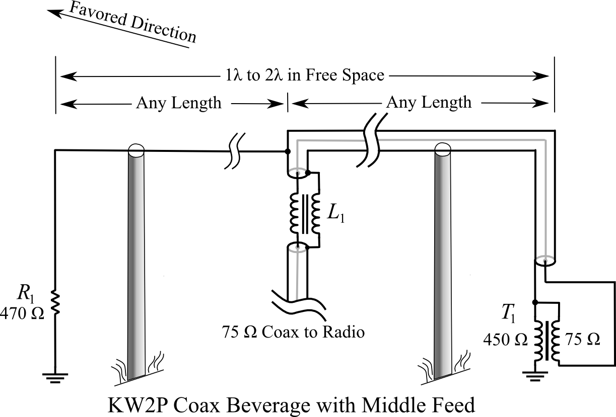
EMBODIMENT TWO: Feed it anywhere.
It’s probably obvious to some readers that since the coaxial cable (in terms of the signal traveling on the inside) is untuned, its length does not matter. The coax does not have to continue for the full length of the Beverage antenna as shown above and the feedline can be brought off at any point. The advantages of this are clear. Instead of worrying about where the endpoints of the antenna are with respect to the shack, all the antenna has to do is pass nearby the shack and the feed is brought off at the nearest point. Several Beverages covering different directions can be installed and as long as they pass near the shack at some point the feedlines can all be very short.
EMBODIMENT THREE: Reversible KW2P Beverage
This variation may also be obvious to some readers. Note that I have never built and tested this variation but I have no doubt that it would work fine. I’m hoping to find and acquire a piece of land large enough to try this out.
Reversible Beverages invariably have relay boxes at the far ends of the antenna to switch between feedline and terminating resistor in order to reverse the antenna pattern. The concepts shown above in embodiment two demonstrate bringing the feedline off at any point along the antenna’s length. The same method can be employed to bring the terminating resistor to certain points along the antenna or all the way to the opposite end. Directional switching can take place in a single box located at either end of the antenna or at certain points along the antenna’s length. Switching directions is simply a matter of swapping the feedline for the resistor at L1 and L2.
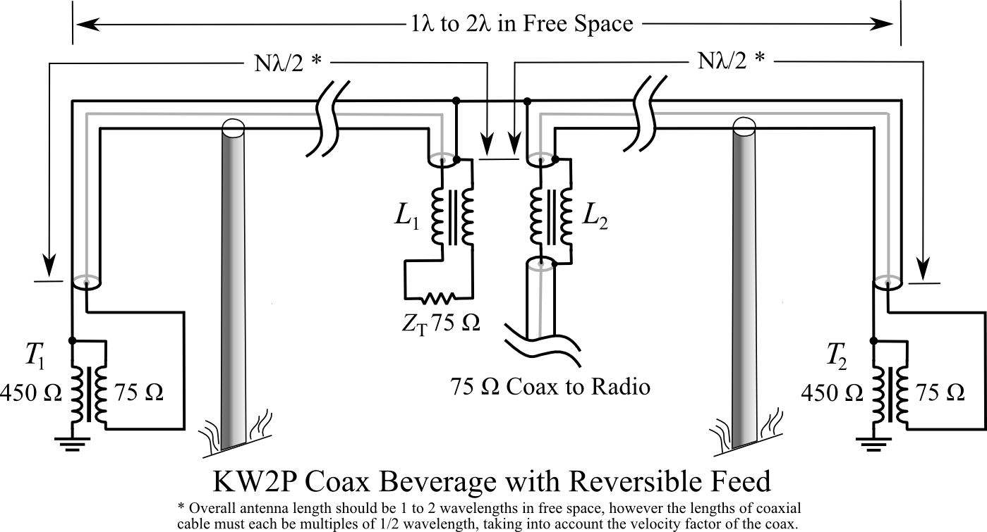
Now comes a question: Note that in the first two embodiments, the length of the coaxial cable(s) did not matter. In this third embodiment, I assume that the lengths of coax are halfwave multiples (electrical length), taking into account the velocity factor of the coax (inside). The reason for the 1/2 wavelength multiples is to ensure that the resistance of the termination resistor is reflected accurately at the other end of the coax as a pure resistance. However, if the impedances of the Beverage wire / matching transformers / coaxial cables are all matched closely enough that SWR inside the coax is low, the lengths should not matter and it should not be necessary to hold to 1/2 wavelength multiples. This remains to be tested empirically.
Lightning Survivability
One thing to consider when building Beverages is ease of construction and low cost of components like transformers and baluns because these components are frequently destroyed by lightning. A Beverage is a very long wire so lightning strikes hundreds of feet away can still induce plenty of current to vaporize baluns and transformers, puncture insulation, etc. Spark gaps at strategic locations are inexpensive, low-tech, and well worth the effort. Each support should be equipped with a ground rod and spark gap. Nothing will save you from a direct or very close hit but spark gaps will protect against most of the nearby hits. It is also a good idea to frequently inspect the antenna and spark gaps. A spark gap that was vaporized by yesterday’s storm won’t protect you today.
Matching transformers cannot be made lightning resistant but fortunately they are cheap and easy to make. If you’re going to make one, make several at a time. You’ll probably need them.
Suitable Baluns
There are several ways to build a suitable balun for this antenna. The type of balun needed in these designs is actually an unun (unbalanced-unbalanced), also called a “current balun”, or a Collins balun. What the balun is doing is it simply uses inductance to choke off or block the antenna currents traveling on the outside of the coax, keeping them “up on the antenna wire” and not traveling down the feedline into the shack.
Construction parameters to consider are:
1) Keep inter-turn capacitance as low as possible to keep the self-resonant frequency of the balun as high as possible so the antenna can be used on 80m and even 40m if desired. If operation on bands other than 160m is not planned then self-resonant frequency is not that important as long as f0 is well above 2.0 MHz.
2) Baluns can be and should be designed with lightning surges in mind. A direct hit near the balun will likely destroy it no matter how it’s constructed but most lightning surges will come from induced current from nearby strikes that a properly made balun can withstand. The more surge resistant you make the balun, the less often you will have to replace it. Making the balun more lightning resistant mainly consists of making the balun physically large and distributing the surge voltage across the whole balun so that it doesn’t arc over between turns. The best way to achieve this is with a long solenoid-shaped coil that keeps the first and last turns as far away from each other as possible and distributes the voltage evenly. This also minimizes inter-turn capacitance mentioned above.
Some Numbers for Solenoid Baluns
Here are some numbers for suitable baluns
RG-6
| Form Dia. | Coil Len. | Turns | uH | Coax Len Ft |
| 4.5 in | 56 in** | 168 | 246 | 198 |
| 12 in | 11 in | 33 | 239 | 104 |
| 12 in | 18 in | 54 | 448 | 169 |
| 18 in | 7.3 in | 22 | 254 | 104 |
| 18 in | 11 in | 33 | 461 | 155 |
RG-8X, RG-59
| Form Dia. | Coil Len. | Turns | uH | Coax Len Ft |
| 4.5 in | 30 in | 124 | 243 | 146 |
| 12 in | 7 in | 29 | 244 | 91 |
| 12 in | 11 in | 46 | 464 | 144 |
| 18 in | 5 in | 20 | 247 | 94 |
| 18 in | 7 in | 29 | 451 | 136 |
RG-58
| Form Dia. | Coil Len. | Turns | uH | Coax Len Ft |
| 4.5 in | 21 in | 107 | 251 | 126 |
| 4.5 in | 36 in | 185 | 456 | 218 |
| 12 in | 5.3 in | 27 | 246 | 85 |
| 12 in | 8 in | 41 | 452 | 129 |
| 18 in | 3.7 | 19 | 248 | 89 |
| 18 in | 5.3 | 27 | 441 | 127 |
RG-174
| Form Dia. | Coil Len. | Turns | uH | Coax Len Ft |
| 4.5 in | 6.5 in | 65 | 251 | 76 |
| 4.5 in | 10.5 | 105 | 446 | 124 |
| 12 in | 2.3 | 23 | 247 | 72 |
| 12 in | 3.3 | 33 | 451 | 104 |
| 18 in | 1.8 | 18 | 265 | 84 |
| 18 in | 2.4 | 24 | 444 | 113 |
** A single layer of RG-6 on a 4.5 inch form is impractical. One way to cut down on coil length and reduce the amount of coax in the balun is to wind a 2-layer coil. A conventional 2-layer winding that runs to one end, then reverses back over the first layer gives a neat-looking result but is a bad idea. It brings the first turn very close to the last turn and defeats the main reason for winding a solenoid instead of a toroidal or Collins balun: high arc-over resistance. However you can quasi-scramble wind it to keep most of the benefits and reduce the length of the coil. Wind two or three turns on the coil form, then cross back and wind two or three turns in a second layer over the first three turns. Then put three more turns on the form, cross back and put a second layer on those, and so on. It’s not as neat looking but it creates a 2-layer coil that keeps almost all the benefit of a single-layer coil.
Coax losses at 2.0 MHz are shown below. Values are for 150 feet and SWR of 1.5:1. Except for RG-174 miniature coax, losses at 2 MHz are so low they can be ignored.
| Type | Imp | Loss | ||
| RG-6A/U | 75 | 0.604 dB | ||
| RG-8X | 50 | 0.631 dB | ||
| RG-58 | 50 | 0.788 dB | ||
| RG-59 | 75 | 0.678 dB | ||
| RG-59B | 75 | 0.734 dB | ||
| RG-174 | 50 | 1.74 dB |
Collins Baluns
A Collins balun is very easy to make and consumes about half the amount of coax as a solenoid. However, unlike a single-layer solenoid it offers little resistance to arc-over from lightning.
To make a Collins balun, simply wind the coax lightly on a round form, all in one spot, then slide the coax off the form and tape or wire-tie it into a ring. Unless the coax is very limp and pliable, an extra pair of hands from a helper is useful for this step. A slightly tapered form can be handy for sliding the coax off. Small plastic wastebaskets or barrels often have a good shape.
30 turns of RG-6, 12 inches in diameter, yields about 450uH and consumes 94 feet of coax (in contrast to 170 feet for the same inductance on a solenoid)
Toroidal Baluns
Toroidal baluns can also be used with these antennas. These antennas are receive-only so there are no issues of saturation or power handling. The target inductance is 450 uH so we want to use the highest permeability ferrite that will handle the frequencies of interest. Good old Type 43 is probably the best choice. It has a permeability around 850+ and handles 160, 80, and 40 meter frequencies. An FT-240-43 core yields 450 uH with 20 turns. The problem is the window of this core is 1.4 inches in diameter so it will only accommodate 12 turns of RG-6 (0.332″ dia.). Stacking two cores reduces the required number of turns to 15, but that’s still too many. Since the balun is really just an inductor, and inductors in series add together, we can get even closer to the goal with two 225 uH baluns in series. This gets the number of turns required down to 13 on each core which is still more than the 12 turns that will fit, but close enough.
Building the balun with RG-59 (0.242″ dia.) coax solves the window area problem because 19 turns fits easily through a 1.4 inch window. And only one core is needed instead of two, which may be a concern because FT-240-43 cores cost about 10 dollars apiece.
The best solution in my opinion is to use RG-174. It only takes about a couple of feet of RG-174 for 20 turns. The added loss of a couple feet of RG-174 can be ignored.
While a toroidal balun will work fine it provides almost no lightning protection and be prepared to replace ones damaged by lightning.
I hope these Beverage designs can be of use to other hams, make your installations easier to build, easier to maintain, cheaper, and more reliable.
Where you helpfully suggest, “Each support should be equipped with a ground rod and spark gap,” do I understand correctly that said gap is to between said ground rod and the coax shield? How best is this accomplished. Have you a photo?
Hello. It’s been 25 years since I had enough space to run Beverage antennas. All photos of my contesting setup were lost and I doubt I ever took detail photos like that anyway. There are lots of ways you might do it. My supports were “peeler poles” normally used to make fences. From the ground rod I ran 8 gauge aluminum wire up the pole, just stapled to the pole. At the top I left about four inches of wire sticking past the end of the pole that I bent so the sharp tip of the aluminum wire was about 1/4 inch from the coax.
From time to time, I’d walk the full length of the antennas with a stepladder and inspect each support and both ends. Since I was located in the desert, I never had any lightning problems, but I was prepared for it. My work at the time sometimes involved repairing the aftermath of lightning damage to equipment so I was sensitive to the problem. My longer term plans involve moving to the tropics where lightning is frequent and powerful, and I hope to put up Beverages. Beverage antennas are just asking for trouble from lightning so we’ll see how that works out. Hah. I would expect the little transformers to be expendibles, frequently destroyed by lightning surges.
I suppose that the terminating transformer T1, T2 are 1:9 and the buluns could be replaced with 1:1 isolation transformer, right?
No, you want the impedance transformation. That’s why I labeled the drawings as I did. A Beverage has an impedance of around 800 ohms and you need to match that to 50 or 75 ohm coax. But it can be approximate. I’ve used 1:1 transformers and no transformer in an emergency and it worked. But it will work better with a transformer.
Since these are not transmitting antennas, there’s no need to bother with the complexity of a 9:1 transmission line transformer wound on expensive ferrite, etc. Just a simple transformer with a 3:1 turns ratio of small gauge wire on a cheap small powdered iron core the size of your fingernail is all that’s needed.