This has only been tested on the UV-5R and UV-S9Plus. This may also work with other models.
Programming the channels of Baofeng radios is straightforward using CHIRP. That’s great, but it seems to me that a radio that requires a computer and a special cable to program is pretty useless in the field.
The general belief is that manual programming of these radios is difficult. I can understand why. I spent several hours fiddling around. I studied various tutorials and followed step by step instructions without success. Putting together bits I’ve learned with some experimentation, I have the following sequences that work without fail for me.
Programming these radios isn’t difficult, just a little odd in comparison to my Yaesu FT-60. The main difference is that to program a duplex channel on the Yaesu, you set everything up in VFO mode, transmit and receive frequencies, CTCSS, etc. Then in one step you transfer all of it into a memory channel.
With the Baofeng, you start out the same way, setting up everything in the VFO, but storing it is a two step process. The receive and transmit parameters are stored in two steps by storing to the same memory channel twice. This can be tricky but I found a straightforward way to do it that’s easy to remember. At the end I include a little “theory of operation” that might help you visualize what’s happening.
FIRST
Before following either the SIMPLEX or DUPLEX procedures below, erase the contents of the memory channel you want to program. Let’s say you want to erase memory channel 5.
MENU (to enter menu mode) DEL-CH (select the DEL-CH function, use arrows or enter 28) MENU (to enter the delete channel function) Select the channel with arrows or numeric entry MENU (to perform the memory delete operation) EXIT (to exit menu mode)
Note that the DEL-CH and MEM-CH functions display a 3-digit channel number. If the number is preceded by CH, like CH005, then the memory is in use. If the channel number is plain like 005, the channel is empty and can be programmed.
SIMPLEX PROGRAMMING
Switch to VFO mode and the upper display (A), and enter the frequency you want to store. Then perform the following steps.
MENU (To enter menu mode) MEM-CH (select the MEM-CH function, use arrows or enter 27) MENU (to select the MEM-CH function) Select the channel using arrows or numeric entry MENU (to perform the memory store operation) EXIT (to exit menu mode)
Now switch from VFO to memory mode (VFO/MR), select your new channel and test it.
DUPLEX PROGRAMMING
Remember to delete the channel you want to program, described in the first step above.
Switch to VFO mode and the upper display (A). Since we’re talking duplex, you’re probably trying to set up a channel for a repeater and will need to program offset and CTCSS. I’ll show all of the steps below.
First, enter the downlink frequency (the frequency you listen to). Let’s say it’s 146.685. Enter 146685 and it should display on the upper (A) VFO.
Let’s say the repeater has a negative offset of 600 kHz (input is at 146.085) and an input PL tone or CTCSS of 103.5 Hz, no downlink PL, no DCS. So your radio must transmit a 103.5 Hz tone to break the squelch on the repeater.
MENU (to enter menu mode) R-DCS (select R-DCS function using arrows or enter 10) MENU (to select the function) Use arrow keys to turn this off MENU (to perform the operation)
R-CTCS (select R-CTCS function using arrows or enter 11) MENU (to select the function) Use arrow keys to turn this off. (If your repeater has downlink PL and you want to try using it, then set this to the right frequency. I would leave it off for now and experiment later.) MENU (to perform the operation)
T-DCS (select T-DCS function using arrows or enter 12) MENU (to select the function) Use arrow keys to turn this off. MENU (to perform the operation)
T-CTCS (select T-CTCS function using arrows or enter 13) MENU (to select the function) Use arrow keys to select 103.5 Hz (or your repeater’s CTCSS tone frequency) MENU (to perform the operation)
SFT-D (select the shift direction function using arrows or enter 25) MENU (to select the function) Use arrow keys to select + or – shift/offset. Our example repeater is minus. MENU (to perform the operation)
OFFSET (select the offset function using arrows or enter 26) Enter the six digit offset. Note that the display is in Mhz! So the 600 kHz offset of our example repeater is 000600. MENU (to perform the operation) EXIT (exit menu mode)
Once you’ve become accustomed to programming the radio, some of the parameters above will already be set and can be skipped or just checked.
At this point you can test your VFO settings and make sure you can use the repeater. If all is working properly, the next steps will program the channel. (which you have previously erased as described in the first step above.) Let’s say channel 5 is your target. Do not skip any steps below.
MENU (enter menu mode) MEM-CH (select the MEM-CH function using arrow keys or enter 27) Select channel 5. It should display 005 not CH005. If it shows the latter, you failed to delete the channel as instructed in the first step above. You must delete the channel before attempting to program it. You can probably delete it now using the DEL-CH function, 28, but this has not been tested throughly.) MENU (to perform the store to receive memory operation) EXIT (to exit menu mode)
Momentarily press the *SCAN key. This engages “reverse mode” that will flip the transmit and receive frequencies in the VFO so that the transmit frequency is now displayed in A.
MENU (enter menu mode) MEM-CH (should already be selected and since it already has a receive frequency but no transmit frequency, will display CH005. This is correct.) MENU (to perform the transmit memory store operation) EXIT
Switch to memory/channel mode VFO/MR and test your new channel.
The above is the “magic sequence” that makes it easy. If you have everything set up in the VFO, and the target channel is already deleted, the sequence is:
MENU MEM-CH Select channel MENU EXIT *SCAN MENU MENU EXIT
Once accustomed to it, you can delete the channel, set up the frequency, PL tone, offset, offset direction, and program the channel in well under a minute.
Theory of Operation
Each memory channel has space for a receive frequency with its associated parameters, and a transmit frequency with its associated parameters. When you delete a channel, it clears both.
When you store a frequency and its parameters into an empty channel, the information gets stored in the receive space. When you store a frequency and parameters a second time to the same memory channel, that information gets stored in the transmit space. So it takes two steps to program a duplex channel because they have different transmit and receive frequencies.
Storing a simplex channel only requires the first step. You store the frequency and parameters once and they reside in the receive space. If you transmit on a channel that only has the receive space programmed, the radio will transmit on the receive frequency, and you have simplex.
In other words, if only the receive space of a channel is programmed and the transmit space is blank, then the channel is treated as simplex. It will transmit and receive on the receive frequency. If both receive and transmit spaces of a memory channel are programmed, the radio will operate duplex on the two different frequencies.
The short answer is that SKCC is possibly the greatest ham radio organization since the ARRL. The Straight Key Century Club or SKCC was created in 2006. History of the organization is well documented here: https://www.skccgroup.com/member_services/club_history/
SKCC is composed of tens of thousands of hams who love doing “manual”(1) Morse Code (CW), who recognize that the early stages of learning CW are not easy, and who are willing to do whatever it takes to help others learn this skill. Nobody is born with CW skill and SKCC members have not forgotten the time when they too were struggling with code at 3 to 5 words per minute. The SKCC segments in each band are safe places where beginners are welcome.
SKCC provides a wonderfully designed environment that promotes the use of CW. CW skill is built up by one thing only and that’s doing it — sending and receiving in a conversation. Reading about it, thinking about it, or owning lots of keys doesn’t improve your code. Nor does spinning across the band looking for a suitable contact improve your code. A lot of time can be wasted on the latter, time that would be better spent sending receiving code in conversation with a real person. SKCC provides all the ingredients for solving this problem.
SKCC has a large membership and an excellent sked / chat facility on the web where SKCC members can announce their presence and connect with other members for QSOs. There are many levels to membership that are earned by making contacts with other SKCC members. There is an extensive awards program for WAS, DXCC, QRP, types of keys you’ve mastered, ragchewing, and much more, all driven by making contacts. The result is that SKCC is a very active group where all day long you can immediately find people to talk to, people who are highly motivated to make a contact with you because they are chasing one goal or another and need to make contact with you. I’ve never encountered a group / environment that is as well thought out as SKCC and it works really well.
My own story of coming to SKCC is perhaps a bit unusual yet SKCC is just what I needed. In the 1990s I built up my Morse Code ability solely for the purpose of contesting. I drilled myself on copying callsigns and exchanges at high speed using programs like RUFZ. Sending was all done by computer with automated exchanges or occasional typing. I never had a single ordinary conversational QSO with anyone. In 1996 I quit contesting and for next 26 years used only digital modes or voice.
In 2021 I resolved to finally learn Morse Code properly and learn to converse. I joined SKCC in July of 2021 but still didn’t get on the air. I had to relearn code. I practiced extensively “offline” and listening to code on the air. Finally on March 3 of 2022, I took the plunge, extremely nervous that I would make a fool out of myself. Whoever heard of an ex-contester who can’t have a normal conversation on CW? Can’t even happen, right? Well it can.
As it turned out, my concerns and cause for nervousness were completely unfounded. Nobody made fun of my early fumbling and mistakes. Now that I’ve been in the SKCC group for a while and have become comfortable with conversational CW, I realize that nobody even noticed my early stumblings(2). I look back on it all today and see that I was a fool for not doing this long, long ago.
If you are hesitating about getting into Morse Code, believing you can’t do it or believing that people will roll their eyes if you make a mistake, don’t. Neither is true. Don’t be like me, putting it off for one reason or another. The human mind is great at coming up with endless excuses to procrastinate. Today, I’m kicking myself for not doing it years sooner. Just in the short time I’ve been participating with SKCC, I’ve run into several people who, like me, are kicking themselves for not doing it sooner. Please don’t become another one like me.
If you have any interest in “someday” learning CW, do it now. Join SKCC and jump in: https://www.skccgroup.com/ Do it now.
Footnotes:
(1) By manual CW I mean doing it by hand using mechanical keys without electronic assistance. To log an “official” SKCC contact one must use a mechanical key such as a straight key, sideswiper or Vibroplex type bug. No electronic keyer paddles or keyboards.
(2) I’ve learned quite a number of surprising (to me) things about Morse Code. One of them is that copying code that is malformed or that contains errors is not difficult. My experience with code in the 1990s was exclusively with perfect machine generated code with no errors and perfect timing. Earlier this year when I first tried to copy code that was less than perfectly formed, it was jarring and in some cases uncopyable for me. I had to spin the dial. This prevented me from calling CQ for a while.
When searching for contacts I can pick and choose. When calling CQ, anyone might answer. What if I can’t copy them? That would be awful. But I noticed that the errors didn’t seem to prevent conversation with others. What’s going on here? Obviously, the problem was me, but how to fix it? Turns out the problem fixed itself, and quickly.
The human brain is an amazing thing. I discovered that as my skill improved, copying code with poor timing and lots of errors quickly became effortless. Someone might send the letter “P” but with a delayed final dit. Out of context it sounds like “WE”. But the brain copies conversational code IN context and it sounds like a P with a delayed final dit, not WE. It’s not a head-scratcher, it’s hardly noticeable. So all my early concerns and nervousness about sending and receiving imperfect code were unfounded. Don’t let perfection stop you. Nobody sends perfect code and it’s fine.
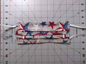
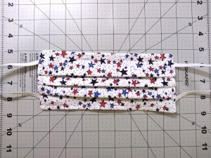
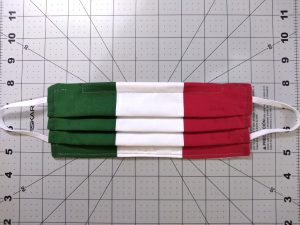
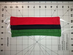
With the pandemic coming, and knowing the effectiveness and importance of masks, I got busy making top quality re-usable ones around the end of March. These are made from top quality fabrics and offered in a standard 2-layer version and high-performance 3-layer masks. They are available for purchase here:
After numerous experiments, I determined that pure cotton muslin is the most comfortable inner liner and this is used on all my masks. Attractive outer designs of high density cotton are available in various styles. Ear bands are comfortable 1/4-inch elastic. All materials are pre-shrunk.
Masks are equipped with a 6-inch wide padded annealed copper nose wire to conform the mask to the shape of your nose and face. This stops leakage and fogging of eyeglasses, and improves filtration effectiveness.
High-performance masks include a third inner layer that serves as an electrostatic filter. These masks deliver 97 to 98 percent filtration efficiency on particles as small as 10 nanometers.
The science behind it and test results are published by the American Chemical Society here:
There are about 30 designs and more are added to the eBay listing every few days. The most recent additions are hand-sewn Italian, Guatemalan, and Pan-African masks.
Hello everyone. So, what have I been up to for most of 2019? No posts here because I’ve not been doing much ham radio besides working on ideas and designs. The short story is I’ve been working at cleaning up the mess from a rather disastrous 2018. And, much of the mess still remains.
The good news is that for the past couple months I’ve been finding some time here and there to work on ham radio pursuits. I’m also doing one of the best things for getting back into the hobby, and that’s “Elmering”. I’ve become friends with a new ham, KE8NBP, Jason, who recently passed his General. Yay, Jason! Jason’s father was a ham, so he already had a pretty good idea of what the hobby is about. Besides teaching him some basic physics, electricity, and stuff about transmission lines, antennas, and so forth, we’ve been talking about Field Day. We’re working towards putting together a 2B operation in some remote spot here in West Virginia. That would be fun.
Unfortunately, I left my entire ham station in storage in Montana, so I have to rebuild from scratch. But that’s something I’ve done a half dozen times now, so I’m experienced at it.
Jason and I are also considering doing additional portable operations, not just on Field Day. I mean, if we build a 2B Field Day setup, why not use it as much as possible? The main reason for this thinking is that Clarksburg, WV is an old Rust Belt town, falling apart, including the electric power distribution system. The electrical noise is the worst I’ve ever seen anywhere. Cracked insulators, arcing connections, and kudzu growing up power poles and sizzling on the wires are common. The last time I operated HF here, power line noise was never less than +10 dB over S9. Digital modes like PSK can manage to some degree with noise like that so that’s what I used. Since then, it’s gotten worse. Jason lives about two miles from me and has a terrible situation because 375 kV marching giants cross directly over his home. He can’t hear anything on HF with a +30 over noise level.
The only solution is some portable operations where it’s quieter. Maybe we could activate some rare counties and so forth.
Anyway, that’s the news from KW2P. More to follow as progress is made.
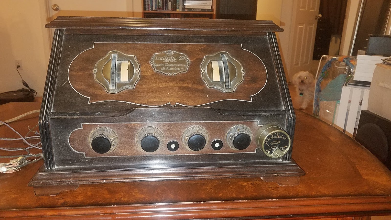
As one might guess, I love radio. I grew up surrounded by vacuum tube equipment and I love old vacuum tube radios. When my friend, Todd, mentioned that a 1925 vintage RCA Radiola 20 was coming into his possession, and he wanted to restore it, I was more than a little interested. Todd had known this radio since childhood, but had never seen it in operation.
Todd is a broadcast engineer with decades of experience operating, repairing, installing, and upgrading AM and FM broadcast radio transmitters. Radio is in his blood.
From 1973 to 1978, I ran a Hammond Organ repair business in Los Angeles, which found me constantly working on vacuum tube equipment, sometimes dating back to the mid-1930s. The Radiola 20 is ten years older than that. Technology improved very quickly in those days. The tubes used in the Radiola in 1925 were already obsolete by 1931. Since the Radiola operated on primary batteries (dry cells), it was designed for minimum power consumption. This radio will not help warm your sitting room, it runs cold. There was much to be learned here and we were both very excited.
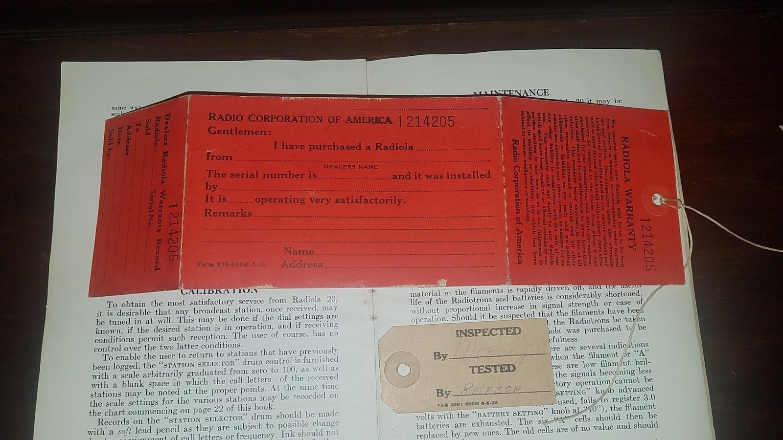
While we were waiting for the radio to ship and arrive, we did research on every aspect of the radio we could find. It took a lot of digging on the Internet and we assembled pretty much everything there is to know and every bit of documentation and literature ever published about the Radiola 20. We found the owners manual and setup guide, RCA’s schematics, technical notes, service notes, and troubleshooting guide for radio repairmen, plus more service notes published by Gernsback. We also drew a modern style schematic using KiCAD. When the radio arrived, Todd found it to be in near pristine condition, like new, and all the original paperwork that came with it was there, including the warranty card. This was a museum quality radio perfect for taking modern color photos of the internals.
Original warranty registration card, never sent in, and inspection tag.
With all this information we collected on our hands, we decided to share it here in one place for others to use. A blog is not the ideal medium for this but it has the advantage of stability and permanance. While researching this information, we often ran into items that had been published on personal web sites many years before that no longer existed, dead links, and photos that were no longer hosted. It’s sad when that happens. Publishing on Blogger and a private blog should avoid this problem for as long as possible. With luck, one of them will be captured in the Internet Archive.
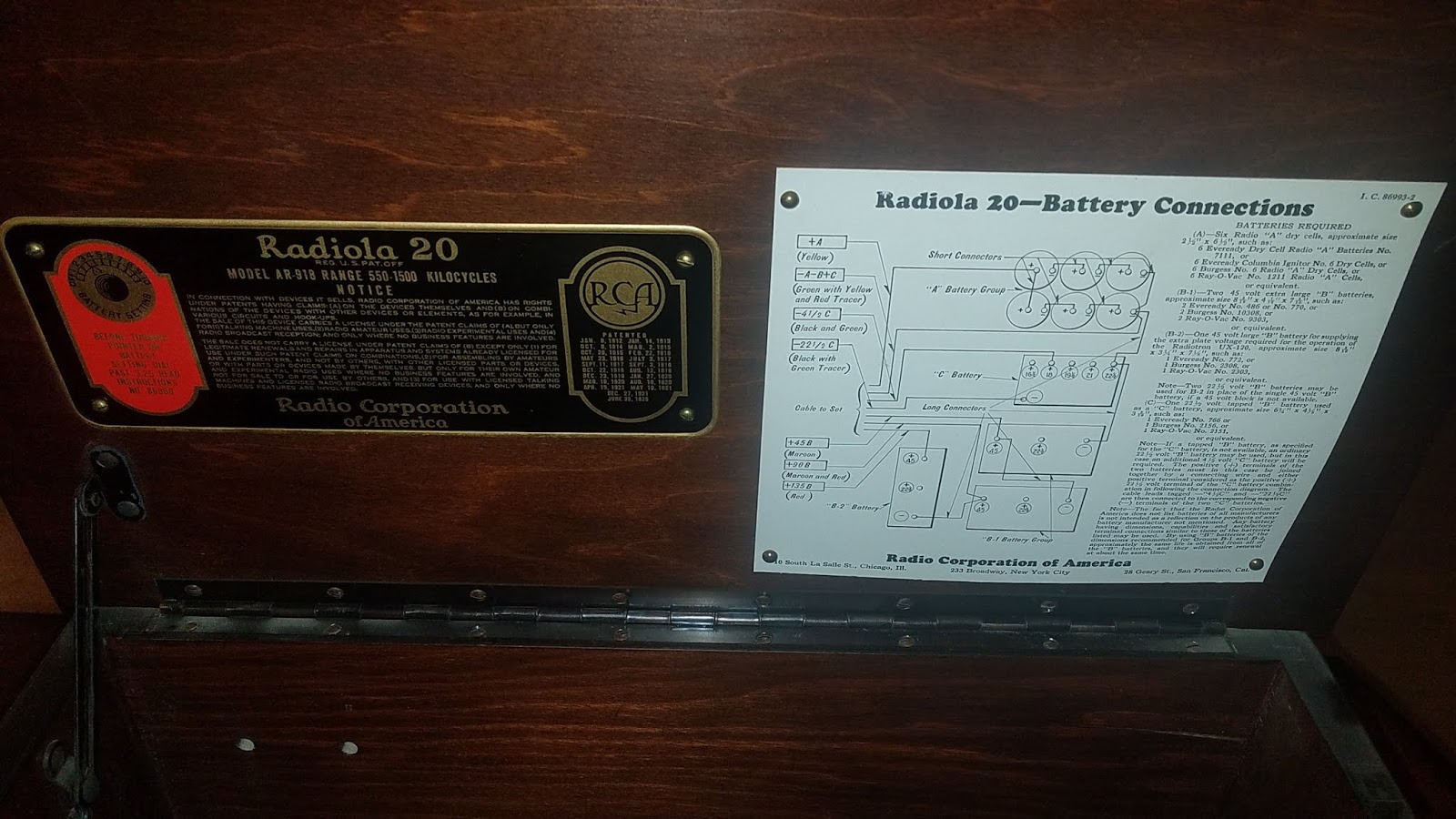
Under the lid is the nameplate and battery connection chart.
Part 2 – The Radiola 20 is Special
Lots of different kinds of radios were being made in 1924, 1925. The RCA Radiola 20 is special because it was the first radio that was both reasonably priced and easy to use. Early radios were difficult to tune and wouldn’t stay on frequency. They required constant fiddling with the controls. At this time, the first superheterodyne radios were appearing. They were easy to use but were large, required a lot of parts, a lot of power, and were priced from $500 to $700 — the price of a new automobile. That’s $7,300 to $10,220 in today’s dollars. Only the wealthy could afford that kind of money for a radio. The Radiola 20 sold for about $100 or $1,460 in today’s dollars. Still, a sizeable purchase, but a lot less than ten grand.
The Radiola 20 is a major engineering achievement and results from the melding of several aspects of radio technology. To appreciate this radio requires a basic grasp of those technologies. This understanding does not require technical knowledge, nor math. Since I don’t know the reader’s knowledge of these things, I will delve briefly into all the background and history leading up to radio, without getting too technical. I’ll also discuss some of the fascinating personalities involved in the development of radio — the birthing ground and foundation of modern electronics.
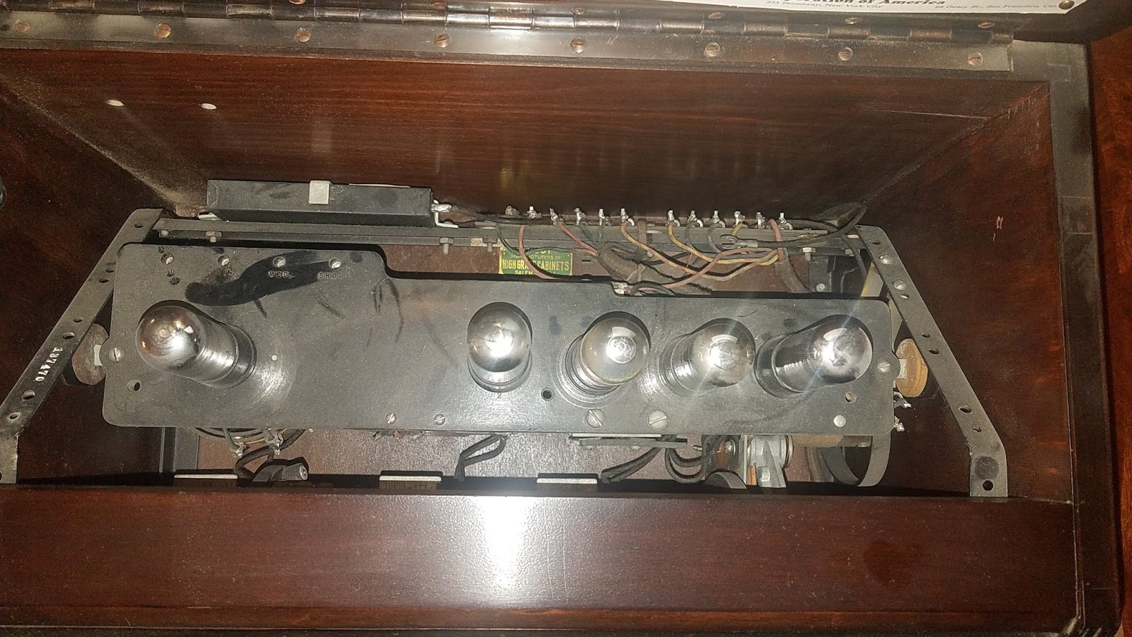
View down into the radio with the top lid open before any work was done.
If you already know the history and different radio design types, you can skip the rest of this section and go to Part 3. If you don’t know, I will cover more detail here than is absolutely necessary, but it will give you a more complete picture.
What I find interesting is how quickly technology develops when consumer demand appears. This is easily seen in the development of radio. Since practical radio and the birth of modern electronics are really the same thing, and both depend on the vacuum tube, I’ll begin with that.
Vacuum tubes are based on a phenomenon called thermionic emission. When an object is heated to incandescence (glowing hot), electrons become free to move and easily leave the surface of the material. This effect becomes noticeable above 1,300 degrees Fahrenheit and was first noted by Bequerel in 1853. If you put an electric charge on an object in dry air, it will hold the charge for a long time. If you then heat the object to 1,300F, it loses the charge. Bequerel observed this but didn’t know why it happened.
Over the next 30 years, the thermionic effect was repeatedly forgotten and rediscovered by different researchers. It was rediscovered again by Edison in 1880 when he was trying to discover why his incandescent lamps seemed sensitive to polarity when run on direct current. When they failed, the positive end of the filament was darkened more than the negative end. The answer was that not all of the current was traveling through the entire filament. Some of the current was somehow traveling through the vacuum in the light bulb and striking the most positive end of the filament. He made special bulbs with an extra electrode inside to measure the effect and it’s named after him: the Edison Effect. He filed a patent for a voltage regulator that used the effect. Edison didn’t see any practical use for it, nor did he understand why it happened. By the way, this was the very first US patent for an electronic (not electrical) device.
Some experimentation with thermionic emission took place over the next 20 years, but not much. The next step was taken by Ambrose Fleming. Since the Edison Effect resulted in conduction in just one direction, a diode, he surmised this might be useful for the detection of radio waves. He was right. It worked better than a crystal, and vastly better than the mechanical cohering detectors used to detect spark transmitter signals in the early 1900s. He patented the diode in 1904. It consisted of a small heated filament, as in a light bulb, and a plate electrode. The device looked liked a small light bulb.
It’s interesting that thermionic emission was not understood until the advent of quantum physics. It was the subject of the 1928 Nobel Prize in physics. Even today, in 2018, physicists still argue over certain fine points that underlie thermionic emission.
At this time, around 1904, the only way to transmit radio waves was with high-voltage spark transmitters or large high-frequency mechanical alternators. These could only be used with Morse Code. There was no speech or music, no audio. Radio was used by the military, by ships at sea, and by radio amateurs (hams). Transmissions were noisy and broad so often only one transmitter in a region could operate at a time because of interference, and there was deliberate jamming. It was chaos.
The next step was a giant one. Lee De Forest was a great promoter of radio with a long and tumultuous career that began in the 1890s. In 1905 and 1906, he was desperately trying to come up with a radio detector that worked well and that didn’t run afoul of the multitude of patents that already existed. He was working with Fleming type diode tubes and wondered what would happen if he inserted a grid of wires between the cathode and anode, and connected the antenna signal to the grid. It worked and he was granted a patent for his invention in 1908. De Forest wasn’t much of a scientist and didn’t understand how it worked, but he had invented the first electronic amplifying device. A small voltage on the control grid could control a much larger current flowing from the filament to the plate electrode.
It is impossible to overstate the importance of this invention — a device capable of power gain. He called his invention the Audion. De Forest himself and many others greatly underestimated the importance of this invention. De Forest thought it might be useful for a few military applications. In fact, it became the fundamental device at the heart of radio, telephone, television, radar, sonar, computers, and countless devices of the electronic age until the transistor was invented in 1947. It took 25 more years, into the late 1960s, for the transistor to largely supplant the vacuum tube. Even today, some applications are best handled by vacuum tubes.
An important detail is that De Forest’s tubes were not made using a “hard” vacuum, but included a small amount of gas. Little attention was paid to impurities inside the glass envelope. Irving Langmuir surmised that many of the problems with triode tubes of the time, such as non-linearity, instability, and limited frequency response resulted from impurities in the envelope. His development of tubes with a hard vacuum inside and scrubbed of all impurities solved the problems. Fleming diodes could only handle low voltages. Langmuir’s could handle hundreds of thousands of volts. Langmuir’s triodes were linear, with higher gain, much higher frequency response, and could handle high voltage. The true vacuum tube was born. This work occurred around 1913 and triggered the rapid adoption of vacuum tubes in long-distance telephone amplifiers. The first transcontinental phone call happened in 1915.
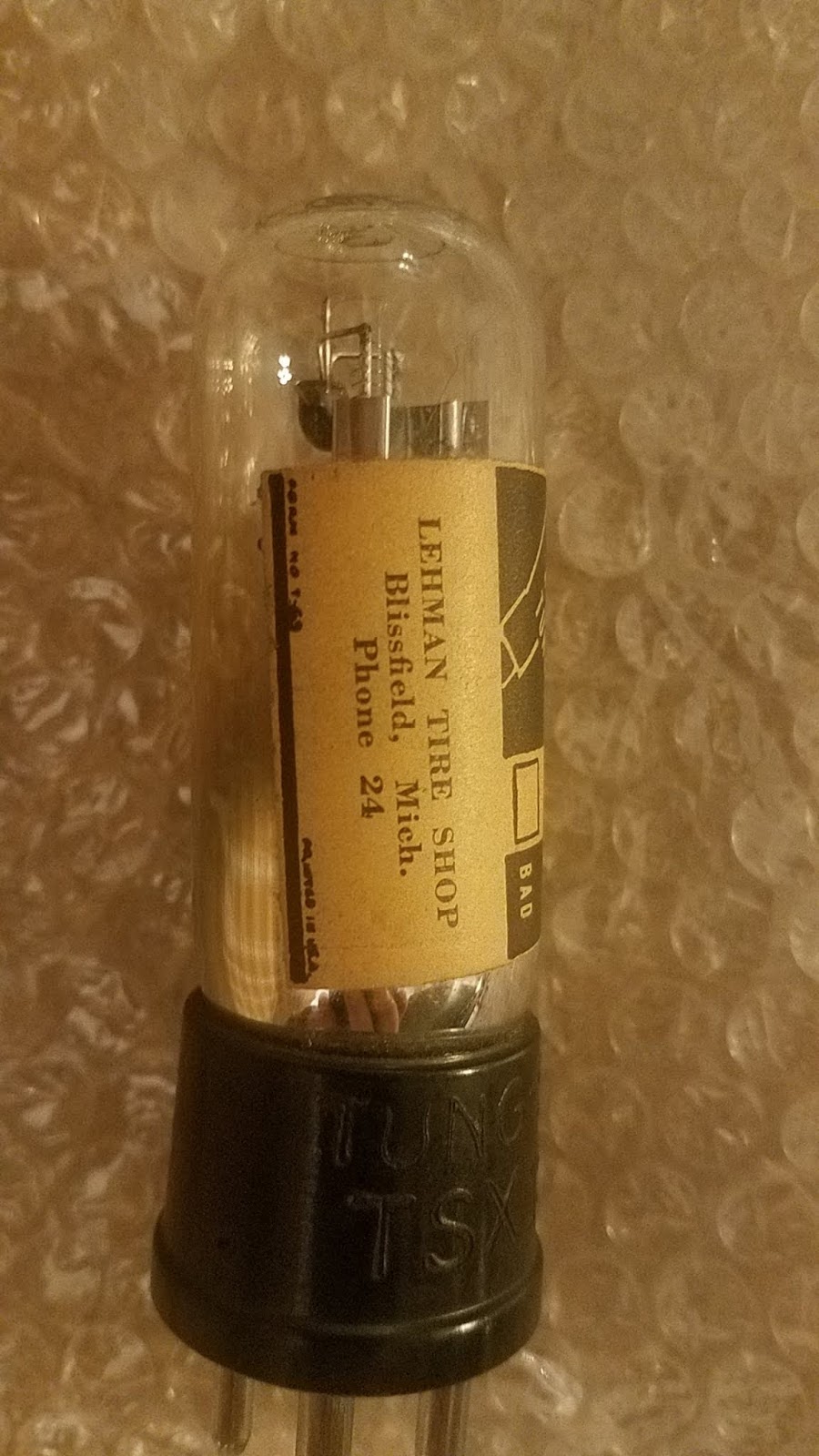
Typical vacuum tube for this radio. There were a few radio and electronics stores but parts were often found in existing stores like this tire shop. Note the phone number: “24”.
Early radio (the electrical era of radio) had many fathers, including Maxwell, Hertz, Tesla, Marconi, De Forest, and others. Modern radio (the electronic era) had just one father, Edwin Armstrong. Every type of radio receiver in use today was invented by Armstrong. In 2018, one can say that every radio device you’ve ever used, from AM, FM, shortwave radios, to cellphones, garage door openers, or wireless thermometers, was either a superheterodyne or superregenerative design. Armstrong was a brilliant scientist and inventor.
While growing up, Armstrong had experimented with the flawed and gassy De Forest audion tubes and desired to gain a full scientific understanding of how they worked, which was unknown. By 1912 there was a basic scientific understanding of vacuum tubes, and it was around this time that Armstrong made his breakthrough invention of “regeneration”.
Audion tubes and early vacuum tubes were primitive and had low performance compared to later vacuum tubes. They had low gain (they amplified, but not by much) and had high interelectrode capacitance, which greatly limited performance. Armstrong discovered that using positive feedback resulted in stunning increases in gain. Instead of an amplifier stage producing a gain of 8 or 10, Armstrong obtained gains of 10,000 and more in a single stage, while using the mediocre tubes of the time. In 1913, Armstrong prepared demonstrations of his invention, scientific papers, and he applied for a patent. The patent issued in October of 1914.
In 1914, Armstrong was an undergraduate at Columbia University, studying electrical engineering. There, he presented the first scientific paper that fully characterized De Forest’s audion tube, complete with oscillographs showing the “characteristic curves”. It amazing that it took six years for someone to do that work. It’s also amazing that the manner in which Armstrong presented the data is the same way we illustrate device data for transistors today.
De Forest discounted Armstrong’s invention and filed a series of competing patents that essentially copied Armstrong’s claims, stating that he discovered regeneration first. Obviously, De Forest realized the importance of the invention. Competing claims were also filed by Alexander Meissner of Germany and Langmuir at General Electric. This was the beginning of many court battles that continued into the 1930s, with lawsuits, and countersuits, and two cases before the US Supreme Court. It seems that whenever there’s an important invention, this happens. In one of the early court cases, Armstrong and De Forest argued face to face. Armstrong easily demonstrated to the court that De Forest hadn’t the faintest idea how his audion tubes worked or how regeneration worked. Yet, the courts finally found in favor of De Forest, which today, is just stunning. The entire engineering community was shocked and appalled, but that’s how it ended up.
Another example of this kind of injustice was Marconi winning the patent battles and the title “Inventor of Radio”. He even won the 1909 Nobel Prize. Fortunately, this miscarriage of justice had a just but too-late outcome. It took 40 years for the courts to finally overturn the previous decisions in favor of Marconi and award inventorship to Nikola Tesla. After all, Tesla was using radio for remote control purposes when Marconi was but a child. However, it was too late and Tesla died penniless.
There are many more examples of such injustices. The takeaway is that the showman always wins. The person who wins is not the smarter person, but the person who is the better promoter, the better politician, the better financier, and the better people-person.
Armstrong’s invention of the regenerative radio was the right invention at the right time. One vacuum tube and a few parts, some of which could be made by hand, resulted in a high-performance radio. Anyone who was interested could afford to make one. What do I mean by high-performance? High-performance means a radio that can capture signals all the way down to the noise floor, the limit of what is possible. (There are modern digital techniques that can get quite a way below the noise floor using computers, but none of that was even dreamt of in 1914.)
What is the noise floor? As you make a radio receiver more and more sensitive, you run into an electrical noise limit that cannot be avoided. Natural and man-made electrical noise sets this limit. In the AM radio band, which is what we’re discussing, this noise floor is quite high. There are 15,000 lightning strokes on Earth every second, and each contributes to the noise. Cars, power lines, and electrical equipment radiate noise. Thermal noise in the antenna adds more. You can’t get around physics. The regenerative radio readily reaches this noise limit. You can’t do any better in terms of sensitivity no matter what kind of radio you design.
But, there are no regenerative radios made today, except by hobbyists for fun. This is because the regen has some major drawbacks. It takes skill to tune a regen. To tune in a signal, you have to operate two controls at once. Once it’s tuned, it’s unstable. Changes in temperature, drafts, wind moving the antenna wire, even your hands near the radio cause the tuning to drift. A regen needs constant readjustment. It was great for pioneer enthusiasts, but it’s not a good consumer product that can be set once and left to play for hours.
In addition to sensitivity, a radio must be selective. It must have a narrow enough bandwidth that you only receive the desired signal and not several others at the same time. If you’ve used a crystal radio in an urban environment with lots of radio stations, you know the problem. No matter what you do, you hear more than one station at the same time. If there is only one strong signal it’s okay. The regenerative radio achieves both high gain and high selectivity using almost no parts. This is great, but it has the instability problems mentioned above and other problems of a technical nature that I won’t get into here.
In 1916, Alexanderson patented the TRF radio (Tuned Radio Frequency). Without regeneration, tubes didn’t provide enough gain for a tuned circuit to be sufficiently selective to receive just one station. His idea was to cascade several stages of tuning and amplification — each feeding the next. This actually works well enough if you cascade five to seven such stages. The problem with the TRF is each stage must be independently tuned to the same frequency or you get almost no signal out the end of the chain. Tuning is extremely challenging and requires great patience. Tuning for a certain signal is a process of successive approximation. TRF radios were equipped with precision dials, so that the settings could be written down and found again later. The TRF works. It’s stable. Once tuned, it stays put. But it’s very user-unfriendly.
Many attempts were made to gang-tune the stages of a TRF. In other words, to drive all the tuning capacitors from a common shaft and a single knob. But it couldn’t be done. The mechanics and precise matching of the capacitors was impossible.
Part 3 – The Radiola 20
Which brings us to the Radiola 20. I haven’t explained the superheterodyne radio, also invented by Armstrong, because it’s not necessary for this story. All consumer AM and FM radios made since 1935 are superhets. The superhet solved all of the above problems, but required a lot of parts, a lot of power, and cost a fortune. In 1924, RCA wanted to come up with a radio that was consumer friendly and didn’t cost a fortune. Armstrong was on the RCA staff when the Radiola 20 was designed, so he surely had a hand in it. RCA came up with an efficient hybrid design that used only three stages of TRF plus a small amount of regeneration. Precision manufacturing of the tuning capacitors and mechanics enabled RCA to achieve usable gang-tuning of three stages of TRF using a single dial. This provided enough selectivity, but not enough gain, so the third TRF stage includes some regeneration. This trick was possible because they had the inventor of regeneration, Armstrong, along with his patents, on staff. Melding these two technologies was clever and effective.
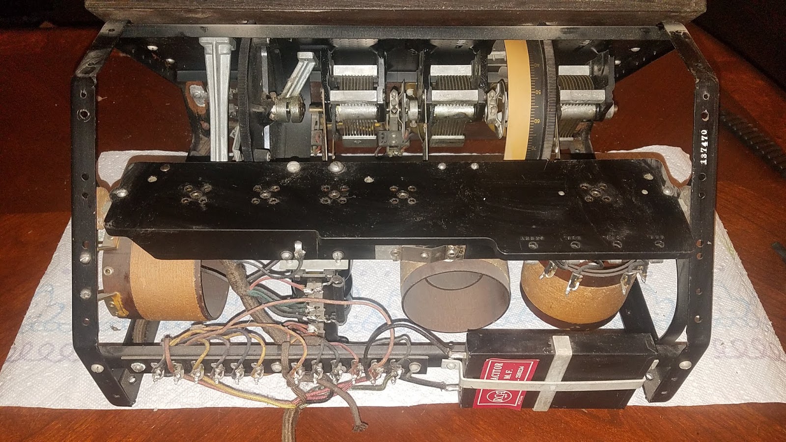
At top are the three TRF tuning capacitors, gang-tuned by a single dial. Below are the three inductors that resonate with the capacitors above. The black panel across the middle contains the vacuum tube sockets. Construction of this radio is unusual, with just a steel frame supporting all the components, and point-to-point wiring.
The result is a radio using only four low-power X-99 tubes, that just sips battery power, that tunes frequency with a single dial. The second dial, called “Amplification” is the regeneration control. Since the tuning is TRF-style, the radio is stable. Tune it once and it plays all day. A fifth vacuum tube is an audio power amplifier that delivers nearly one watt of room-filling audio to the optional speaker. If you’re listening in headphones, you can unplug the fifth tube and save power. The Radiola 20 sold for $115 at introduction in 1925, dropping to $102.50. RCA sold 135,121 of these radios. That’s about $225 million in sales in 2018 dollars.
The Radiola 20 was a radio for the masses. It was affordable and anyone could learn to use it.
If you own one of these pieces of electronic history and are interested in the information we gathered, there’s a link in the comments below. The link enables you to download an 80 MB zip file containing everything we could find on the Radiola 20 and many other radios from that time period.
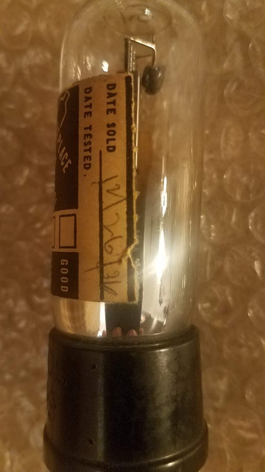
Another vacuum tube. Note the original sale date of December 26, 1936. This is one of the replacement tubes that were acquired because a couple of the original tubes in the radio had lost emission. The only option for replacement is used or rejuvenated tubes.
Recent Comments