In the previous post I showed the loop antenna I’m using at present. Full wave loops will resonate on all harmonics so a 40 meter loop can also be used on 20, 15, and 10 meters, however, you can’t get a perfect match on all bands. What’s more, if the antenna length and feed impedance are adjusted for a perfect 1:1 match on one band, the other bands will suffer. I prefer to go with a “happy medium” approach, where all bands provide an acceptable match. With this antenna that means an SWR of around 2:1. That happy medium occurs, for this antenna, at about 115 ohms.
Below I’ll describe the matching device I built for this antenna and the resulting measurements. The objective for the feed is to match unbalanced 50 ohm coax to a balanced 115 ohm load. The feed shall also choke off or isolate common mode currents so the signal travels inside the coax and not on the shield.
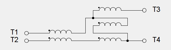
A transmission line transformer configured to transform from one impedance to another is always an unun. It cannot provide isolation. If we also want isolation we must use two separate transmission line transformers in series. In this design, isolation is provided by a transmission line transformer configured as a 50 ohm 1:1 balun followed by a transformer that steps up the impedance. Loss in a well designed transmission line transformer is less than one percent so the combined loss of two in series is still negligible.
We begin with the impedance transforming unun using a T140-61 core and some 16 AWG magnet wire. Type 61 material is more expensive but I chose it for this transformer because it has very low losses from 3 to 30 MHz. This toroid works like an autotransformer so there is some magnetization of the core and low loss is, thus, important.
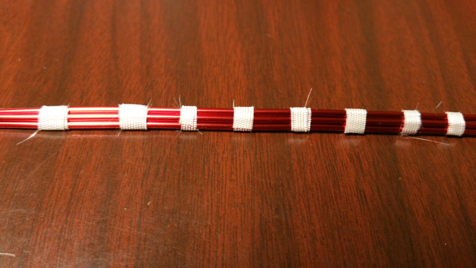
Ferrite is a very hard material so I like to cover toroids with one layer of Scotch 33+ to provide some padding for the wire. This ferrite is non-conductive and the edges are smoothed so the tape probably isn’t necessary but it makes me feel better.
Next, I cut small strips of the fiberglass tape shown above to make the transmission line as shown below. The tape has a silicone adhesive, is rated to over 500 degrees F, and most importantly it doesn’t stretch. Taping the wires like this makes it much easier to wind the toroid core while keeping the conductors side-by-side.
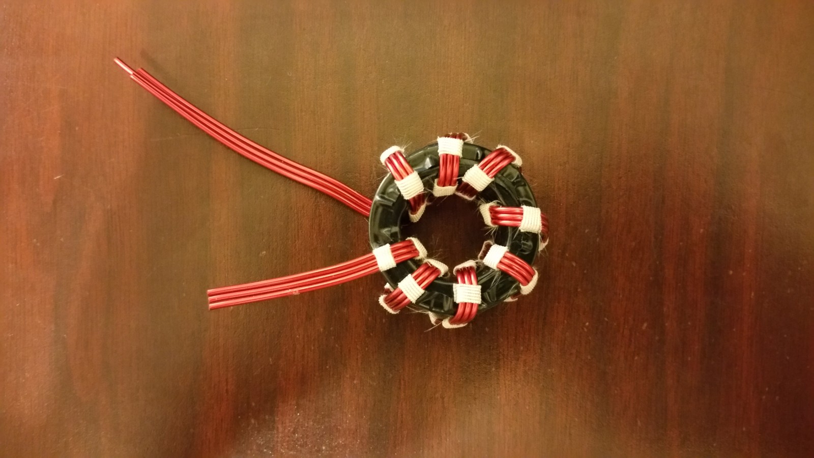
Below is the finished toroid with eight trifilar turns. These will be wired in series and used like an autotransformer with a 1.5 to 1 turns ratio, giving a 2.25 to 1 impedance transformation. In other words, this configuration is a 2.25 to 1 unun, transforming 50 ohms to 112.5 ohms.
FT140-61 toroid with eight trifilar turns
Next we use an FT240-43 toroid and a two conductor transmission line made from 14 AWG magnet wire to make the isolator or 1:1 balun. The objective here is to come up with the highest common mode impedance using the least amount of wire. I chose type 43 material which is cheaper, has much higher permeability, and higher loss, for the following reasons:
We want to minimize inter-turn capacitance in order to keep the self-resonant frequency of the balun as high as possible. That means we want as few turns as possible. Type 61 material has a permeability of 125. Permeability of type 43 is 850, allowing fewer turns to reach a certain inductance.
Type 43 material has higher loss but in this application it doesn’t matter — it’s actually a benefit. Core magnetization in this type of 1:1 balun is theoretically zero. If there’s no core magnetization then there’s no loss. The only core magnetization that might occur results from the small common mode currents that we’re trying to get rid of. If those disappear as heat in the core, so much the better. Core heating in this kind of balun only becomes significant at power levels well beyond 1500 watts so it can be ignored.
Type 43 material costs much less than 61, which is nice, but didn’t drive the choice.
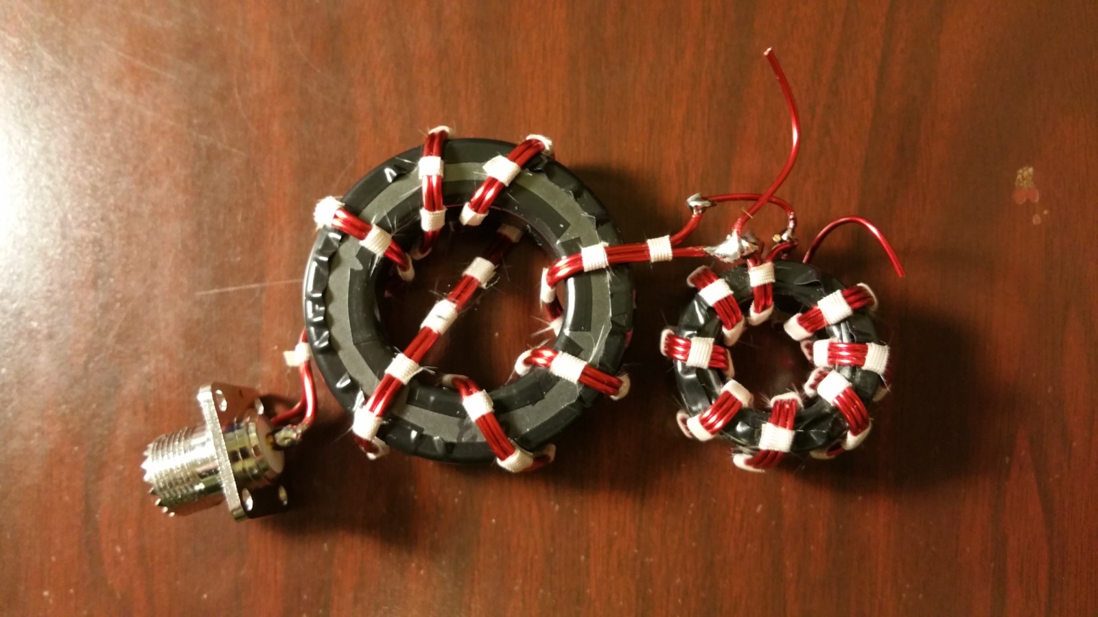
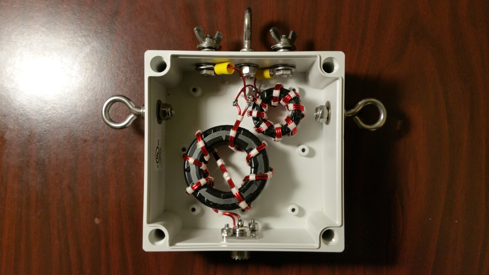
Below is the finished isolator with six turns, connected to the 2.25:1 unun, ready to be installed in an outdoor rated housing. Note the crossover. The crossover has no effect on the performance of the transformer and provides for the input and output wires to come out on opposite sides, which is handy in this case.
Below are the two transmission line transformers installed in a Bud NEMA4 waterproof polycarbonate box. All hardware is 18-8 stainless.
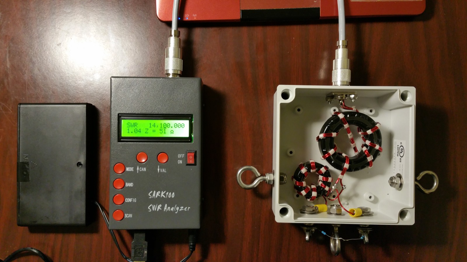
Shown below is the first test setup. A 115 ohm 1% resistor is fixed across the balanced output terminals and the analyzer was swept, taking 500 samples from 3 to 30 MHz. SWR measured nearly flat with 1.01 at 3 MHz, rising to 1.09 at 30 MHz. The photo shows the analyzer at 14.1 MHz reading 51 ohms, exactly what one would expect with 115 ohms on the output terminals.
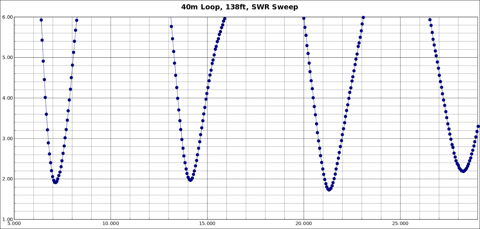
Below is a 500 sample sweep from 3 to 30 MHz of the final installation. I originally made the antenna using 143 feet of wire, which in my experience is a little long so I can trim it. Because this installation has one leg of the triangle parallel to and 10 feet off the slope of the hill behind my house. The antenna resonated about 3 percent low. My calculation said to shorten it by 5 feet, which brought the antenna to exactly where I want it.
The antenna can be used on all four bands without a tuner.
Look for me at night around 7070 kHz on PSK31, Contestia, Olivia, Thor, PSK63F, and Hellschreiber modes. 73 de KW2P.
This QTH is problematic for antennas. The lot is very narrow, just 25 feet. The house is tall, long, and narrow, just 18 feet wide. It’s kind of like living on a sailboat. The attic is impractical to access. There is an attic trap door but it’s too small for an adult to fit through. There is no back yard, just a steep drop behind the house and the front door opens to the sidewalk. Ground radials are not an option. However, there is a tall tree, part way down the hill just behind the house.
My favorite band is 40 meters so that was the main target. I considered several antennas including an end-fed wire, an off-center fed wire, a vertical dipole, a C-pole, and a loop. Modeling the various antennas with NEC2, the C-pole for 40 meters looked promising. It’s shorter than a dipole and needs no radials but it’s a single-band antenna.
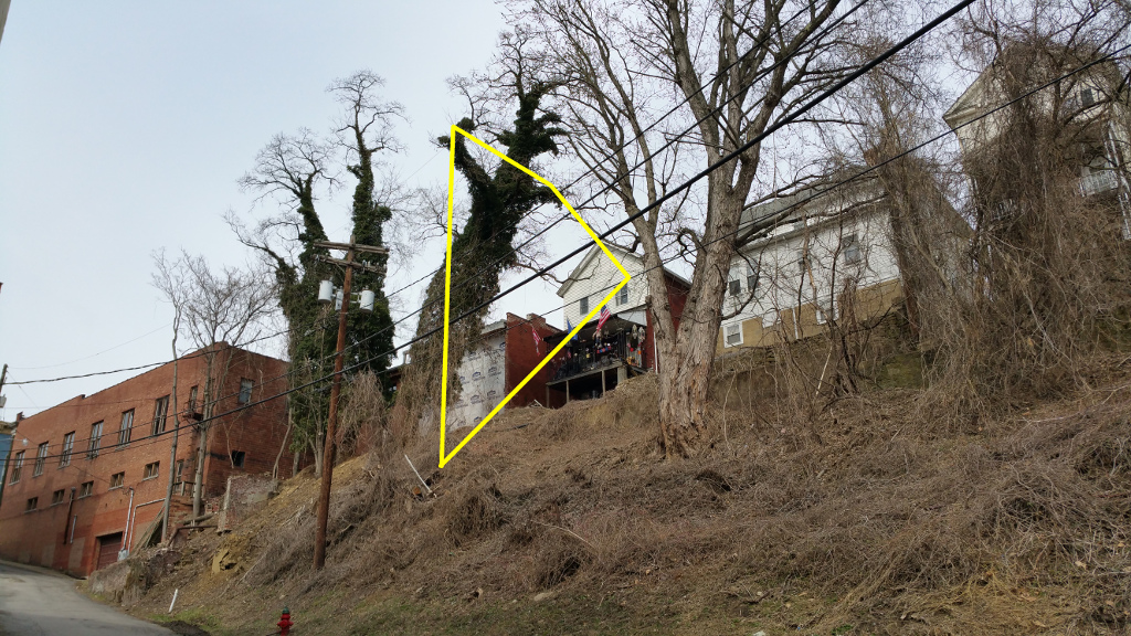
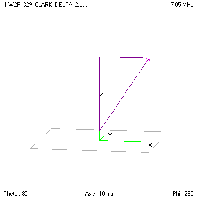
I decided to go with my favorite antenna, the full wavelength loop. The question was if 143 feet of wire could be made to fit. Loops work well, are easy to tune, have high radiation efficiency, and work on all harmonics. Using my laser measure I found that there was just enough space for a triangle running from the upstairs window, to the far branch of the tree (40 feet), then down to an insulator, and back up to the feedpoint at the window.
Using my line launcher and a one ounce lead sinker, I shot non-conductive nylon monofilament line through the tree. As expected, it overshot and landed across the power lines behind the house. I slowly pulled the line back off the power lines and lowered the sinker to the ground. There I attached paracord and hauled it up, over the tree, and to the house. With the paracord I hauled into place the 18 AWG copperweld wire for the antenna. Shown below is the configuration.
143 Foot (43.5m) Wire LoopThe photo’s angle gives a false impression of the shape of the loop. The top segment from the tree to the house is actually almost level. It’s impossible to take a straight-on photo of the antenna.The antenna is invisible unless one looks carefully. Even I have a hard time seeing it.
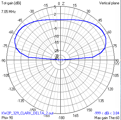
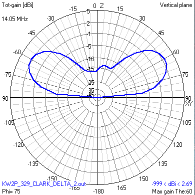
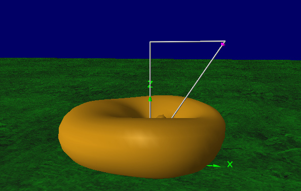
This loop performs very well. Loops almost always do. Below are some plots showing the nearly omnidirectional pattern. Polarization is about 80 percent vertical and 20 percent horizontal.
Antenna Geometry. Feed point is the top right corner.
You’ll find me using digital modes, PSK, Contestia, Olivia, Thor, MFSK16, and Hellschreiber at 7070 and 14070 kHz. I hope to see you on the waterfall! 73 de KW2P.
After a long hiatus, I’m back on the air. QTH: Clarksburg, West Virginia, Harrison County, locator EM99tg. Primary mode is digital. Antenna is a 40 meter vertically oriented triangular loop, which gives good performance on 40, 20, 15, and 10 meters.
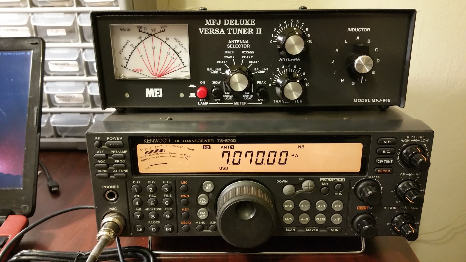
The Rig
I’m also working with my daughter, KC7BNH, in Coeur d’Alene, Idaho, to help get her back on the air as well.
In a perfect world we’d have full-size 160m Beverage antennas fanning out like the spokes of a wheel from a centrally located shack, and the feedpoints would all be located near the shack. Most of us don’t have the necessary 80 acres of land so the feedpoints to our Beverages often end up far away and must be fed through long runs of coaxial cable.
For example, let’s say I want to install a unidirectional Beverage aimed northeast and the shack is located in the northeast corner of the property. The Beverage wire must extend 800 feet towards the southwest of the shack, the termination resistor must be located at the shack end and the feed is all the way at the southwest end. I have to run the 800 foot Beverage wire plus 800 feet of coax to bring the signal to the shack. You can’t do anything to change the geometry of this problem but I’ll show here how the coax can serve both as the feedline and the Beverage wire.
Sometimes we build reversible Beverage antennas that require long runs of coax plus distant relay boxes to perform the required switching. The coax is often buried, making it susceptible to physical damage, especially on farmland, and subject to contamination from constant exposure to moisture. Buried coax can be punctured by nearby lightning strikes. Locating the damage and making repairs can mean replacing the entire run of coax.
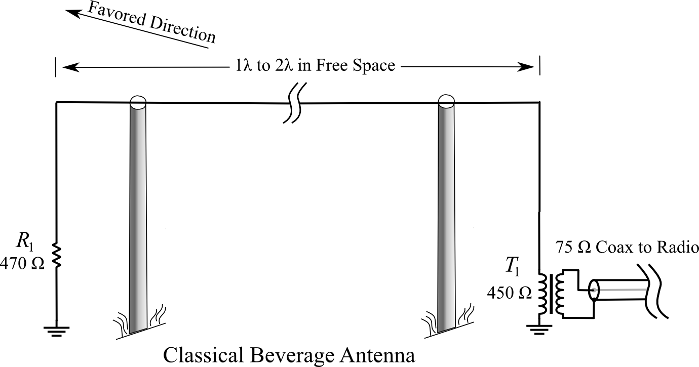
THE CLASSICAL BEVERAGE ANTENNA
Drawing 1, Classical Beverage Antenna. Click to view larger.
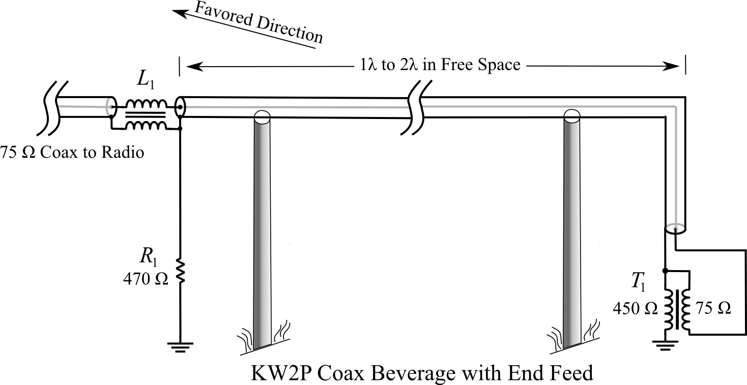
EMBODIMENT ONE: The basic idea.
The basic design concept is shown in the following diagram. The additional embodiments below use the same technique described here. The coaxial cable is suspended above the ground and the outer skin of the coax shield serves as the “wire” of a classical Beverage antenna. The tiny currents induced in the antenna wire (the outer shield of the coax) are referenced to earth ground and are presented to the 450 ohm primary of matching transformer T-1, exactly as in the classical Beverage shown above. T-1’s secondary connects to the shield and center conductor of the coaxial cable feedline, which happens to be the same coax that forms the active element of the antenna. The RF signal injected by T-1 propagates inside the coax to the opposite end (the terminating resistor end) of the antenna. Note that T-1 is an isolation transformer with two independent windings.
Drawing 2, KW2P Coax Beverage with End Feed. Click to view larger.
At the terminating resistor end of the antenna, we are faced with the problem of extracting the signal we want, which is propagating inside the coax, while preventing the RF currents traveling on the outer surface of the coax shield from flowing beyond this point. This is a common problem in antennas that is solved by means of a balun (L1). However the problem in this case is bigger than we usually face with ham antennas. In the case of a Beverage antenna we are likely working at 1.8 MHz, which means the inductances required are large. We are also working with an impedance that is 10 times higher than what we normally work with so the required inductances are that much higher still. (Remember that the balun is concerned with blocking the outside surface currents at the 500 ohm impedance of the Beverage. The 75 or 50 ohm internal impedance of the coax is irrelevant as far as the balun is concerned.)
The rule of thumb for baluns is to present an inductive reactance that is 10 times the impedance we’re working with. For 50 ohm coax you aim at 500 ohms. In this case, the impedance of the Beverage wire is 500 ohms so we’d like to see the balun present 5000 ohms of reactance. At 1.8 MHz, this is a relatively huge amount of inductance–about 450 uH. However, working in our favor is the fact that losses at the terminating resistor end of a Beverage have somewhat less effect on signal output than losses at the feed end of the wire so we can fudge down on the 5000 ohm requirement and call it 2500 ohms. But even so, we are still looking at 225 uH. Suitable baluns are discussed at the end of the article.
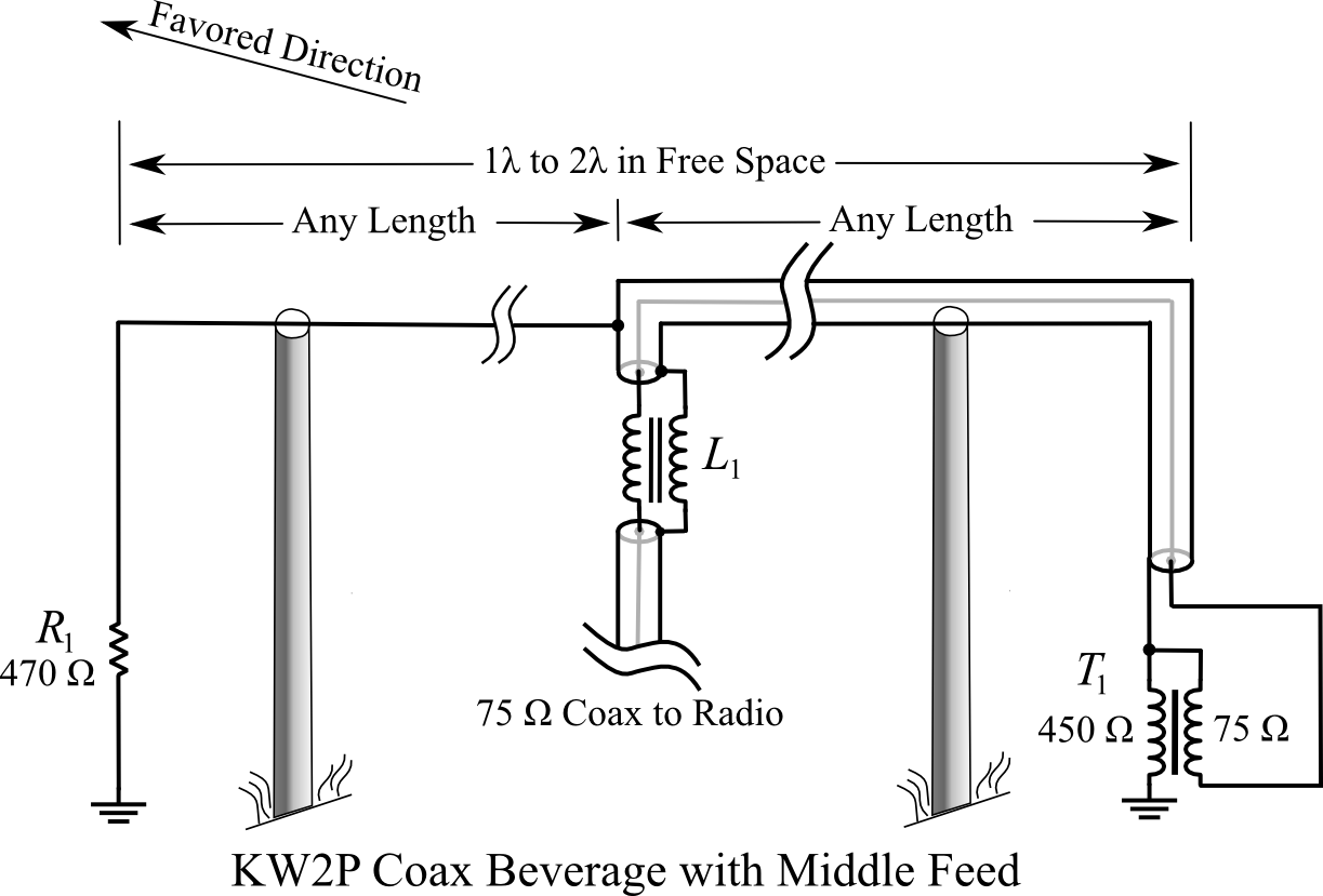
EMBODIMENT TWO: Feed it anywhere.
It’s probably obvious to some readers that since the coaxial cable (in terms of the signal traveling on the inside) is untuned, its length does not matter. The coax does not have to continue for the full length of the Beverage antenna as shown above and the feedline can be brought off at any point. The advantages of this are clear. Instead of worrying about where the endpoints of the antenna are with respect to the shack, all the antenna has to do is pass nearby the shack and the feed is brought off at the nearest point. Several Beverages covering different directions can be installed and as long as they pass near the shack at some point the feedlines can all be very short.
Drawing 3, KW2P Coax Beverage with Middle Feed. Click to view larger.
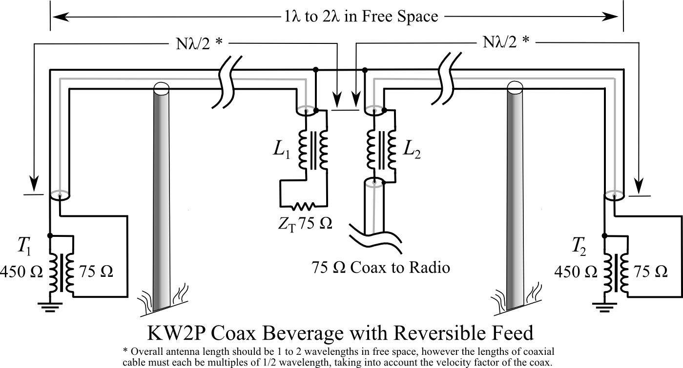
EMBODIMENT THREE: Reversible KW2P Beverage
This variation may also be obvious to some readers. Note that I have never built and tested this variation but I have no doubt that it would work fine. I’m hoping to find and acquire a piece of land large enough to try this out.
Reversible Beverages invariably have relay boxes at the far ends of the antenna to switch between feedline and terminating resistor in order to reverse the antenna pattern. The concepts shown above in embodiment two demonstrate bringing the feedline off at any point along the antenna’s length. The same method can be employed to bring the terminating resistor to certain points along the antenna or all the way to the opposite end. Directional switching can take place in a single box located at either end of the antenna or at certain points along the antenna’s length. Switching directions is simply a matter of swapping the feedline for the resistor at L1 and L2.
Drawing 4, KW2P Coax Beverage with Reversible Feed. Click to view larger.
Now comes a question: Note that in the first two embodiments, the length of the coaxial cable(s) did not matter. In this third embodiment, I assume that the lengths of coax are halfwave multiples (electrical length), taking into account the velocity factor of the coax (inside). The reason for the 1/2 wavelength multiples is to ensure that the resistance of the termination resistor is reflected accurately at the other end of the coax as a pure resistance. However, if the impedances of the Beverage wire / matching transformers / coaxial cables are all matched closely enough that SWR inside the coax is low, the lengths should not matter and it should not be necessary to hold to 1/2 wavelength multiples. This remains to be tested empirically.
Lightning Survivability
One thing to consider when building Beverages is ease of construction and low cost of components like transformers and baluns because these components are frequently destroyed by lightning. A Beverage is a very long wire so lightning strikes hundreds of feet away can still induce plenty of current to vaporize baluns and transformers, puncture insulation, etc. Spark gaps at strategic locations are inexpensive, low-tech, and well worth the effort. Each support should be equipped with a ground rod and spark gap. Nothing will save you from a direct or very close hit but spark gaps will protect against most of the nearby hits. It is also a good idea to frequently inspect the antenna and spark gaps. A spark gap that was vaporized by yesterday’s storm won’t protect you today.
Matching transformers cannot be made lightning resistant but fortunately they are cheap and easy to make. If you’re going to make one, make several at a time. You’ll probably need them.
Suitable Baluns
There are several ways to build a suitable balun for this antenna. The type of balun needed in these designs is actually an unun (unbalanced-unbalanced), also called a “current balun”, or a Collins balun. What the balun is doing is it simply uses inductance to choke off or block the antenna currents traveling on the outside of the coax, keeping them “up on the antenna wire” and not traveling down the feedline into the shack.
Construction parameters to consider are:
1) Keep inter-turn capacitance as low as possible to keep the self-resonant frequency of the balun as high as possible so the antenna can be used on 80m and even 40m if desired. If operation on bands other than 160m is not planned then self-resonant frequency is not that important as long as f0 is well above 2.0 MHz.
2) Baluns can be and should be designed with lightning surges in mind. A direct hit near the balun will likely destroy it no matter how it’s constructed but most lightning surges will come from induced current from nearby strikes that a properly made balun can withstand. The more surge resistant you make the balun, the less often you will have to replace it. Making the balun more lightning resistant mainly consists of making the balun physically large and distributing the surge voltage across the whole balun so that it doesn’t arc over between turns. The best way to achieve this is with a long solenoid-shaped coil that keeps the first and last turns as far away from each other as possible and distributes the voltage evenly. This also minimizes inter-turn capacitance mentioned above.
Some Numbers for Solenoid Baluns
Here are some numbers for suitable baluns
RG-6
Form Dia.
Coil Len.
Turns
uH
Coax Len Ft
4.5 in
56 in**
168
246
198
12 in
11 in
33
239
104
12 in
18 in
54
448
169
18 in
7.3 in
22
254
104
18 in
11 in
33
461
155
RG-8X, RG-59
Form Dia.
Coil Len.
Turns
uH
Coax Len Ft
4.5 in
30 in
124
243
146
12 in
7 in
29
244
91
12 in
11 in
46
464
144
18 in
5 in
20
247
94
18 in
7 in
29
451
136
RG-58
Form Dia.
Coil Len.
Turns
uH
Coax Len Ft
4.5 in
21 in
107
251
126
4.5 in
36 in
185
456
218
12 in
5.3 in
27
246
85
12 in
8 in
41
452
129
18 in
3.7
19
248
89
18 in
5.3
27
441
127
RG-174
Form Dia.
Coil Len.
Turns
uH
Coax Len Ft
4.5 in
6.5 in
65
251
76
4.5 in
10.5
105
446
124
12 in
2.3
23
247
72
12 in
3.3
33
451
104
18 in
1.8
18
265
84
18 in
2.4
24
444
113
** A single layer of RG-6 on a 4.5 inch form is impractical. One way to cut down on coil length and reduce the amount of coax in the balun is to wind a 2-layer coil. A conventional 2-layer winding that runs to one end, then reverses back over the first layer gives a neat-looking result but is a bad idea. It brings the first turn very close to the last turn and defeats the main reason for winding a solenoid instead of a toroidal or Collins balun: high arc-over resistance. However you can quasi-scramble wind it to keep most of the benefits and reduce the length of the coil. Wind two or three turns on the coil form, then cross back and wind two or three turns in a second layer over the first three turns. Then put three more turns on the form, cross back and put a second layer on those, and so on. It’s not as neat looking but it creates a 2-layer coil that keeps almost all the benefit of a single-layer coil.
Coax losses at 2.0 MHz are shown below. Values are for 150 feet and SWR of 1.5:1. Except for RG-174 miniature coax, losses at 2 MHz are so low they can be ignored.
Type
Imp
Loss
RG-6A/U
75
0.604 dB
RG-8X
50
0.631 dB
RG-58
50
0.788 dB
RG-59
75
0.678 dB
RG-59B
75
0.734 dB
RG-174
50
1.74 dB
Collins Baluns
A Collins balun is very easy to make and consumes about half the amount of coax as a solenoid. However, unlike a single-layer solenoid it offers little resistance to arc-over from lightning.
To make a Collins balun, simply wind the coax lightly on a round form, all in one spot, then slide the coax off the form and tape or wire-tie it into a ring. Unless the coax is very limp and pliable, an extra pair of hands from a helper is useful for this step. A slightly tapered form can be handy for sliding the coax off. Small plastic wastebaskets or barrels often have a good shape.
30 turns of RG-6, 12 inches in diameter, yields about 450uH and consumes 94 feet of coax (in contrast to 170 feet for the same inductance on a solenoid)
Toroidal Baluns
Toroidal baluns can also be used with these antennas. These antennas are receive-only so there are no issues of saturation or power handling. The target inductance is 450 uH so we want to use the highest permeability ferrite that will handle the frequencies of interest. Good old Type 43 is probably the best choice. It has a permeability around 850+ and handles 160, 80, and 40 meter frequencies. An FT-240-43 core yields 450 uH with 20 turns. The problem is the window of this core is 1.4 inches in diameter so it will only accommodate 12 turns of RG-6 (0.332″ dia.). Stacking two cores reduces the required number of turns to 15, but that’s still too many. Since the balun is really just an inductor, and inductors in series add together, we can get even closer to the goal with two 225 uH baluns in series. This gets the number of turns required down to 13 on each core which is still more than the 12 turns that will fit, but close enough.
Building the balun with RG-59 (0.242″ dia.) coax solves the window area problem because 19 turns fits easily through a 1.4 inch window. And only one core is needed instead of two, which may be a concern because FT-240-43 cores cost about 10 dollars apiece.
The best solution in my opinion is to use RG-174. It only takes about a couple of feet of RG-174 for 20 turns. The added loss of a couple feet of RG-174 can be ignored.
While a toroidal balun will work fine it provides almost no lightning protection and be prepared to replace ones damaged by lightning.
I hope these Beverage designs can be of use to other hams, make your installations easier to build, easier to maintain, cheaper, and more reliable.
After an interruption in ham radio activities and blog entries, I am back on the air, more or less. The interruption was due to several months of planning and executing a move to Guatemala and then getting settled here in my new digs and setting up a basic radio shack. At the moment I am only using a 26 foot vertical wire supported by a tree so my signal is not very good but I’m out there on PSK and Hellschreiber. You can usually find me evening and nights from 7070 to 7074, signing TG9/KW2P. Give me a call.
Once I collect the materials I plan to put up a 270 foot vertical loop. I have some tall trees here that will support a vertically oriented 80m full wave loop. I’ve had both vertical and horizontal loops of that size and they worked great so I expect good results, especially in the tropics where QRN can be a problem. The loop should improve things drastically but getting the materials down here takes some doing.

Recent Comments