In the previous post I showed the loop antenna I’m using at present. Full wave loops will resonate on all harmonics so a 40 meter loop can also be used on 20, 15, and 10 meters, however, you can’t get a perfect match on all bands. What’s more, if the antenna length and feed impedance are adjusted for a perfect 1:1 match on one band, the other bands will suffer. I prefer to go with a “happy medium” approach, where all bands provide an acceptable match. With this antenna that means an SWR of around 2:1. That happy medium occurs, for this antenna, at about 115 ohms.
Below I’ll describe the matching device I built for this antenna and the resulting measurements. The objective for the feed is to match unbalanced 50 ohm coax to a balanced 115 ohm load. The feed shall also choke off or isolate common mode currents so the signal travels inside the coax and not on the shield.
A transmission line transformer configured to transform from one impedance to another is always an unun. It cannot provide isolation. If we also want isolation we must use two separate transmission line transformers in series. In this design, isolation is provided by a transmission line transformer configured as a 50 ohm 1:1 balun followed by a transformer that steps up the impedance. Loss in a well designed transmission line transformer is less than one percent so the combined loss of two in series is still negligible.
We begin with the impedance transforming unun using a T140-61 core and some 16 AWG magnet wire. Type 61 material is more expensive but I chose it for this transformer because it has very low losses from 3 to 30 MHz. This toroid works like an autotransformer so there is some magnetization of the core and low loss is, thus, important.
Ferrite is a very hard material so I like to cover toroids with one layer of Scotch 33+ to provide some padding for the wire. This ferrite is non-conductive and the edges are smoothed so the tape probably isn’t necessary but it makes me feel better.

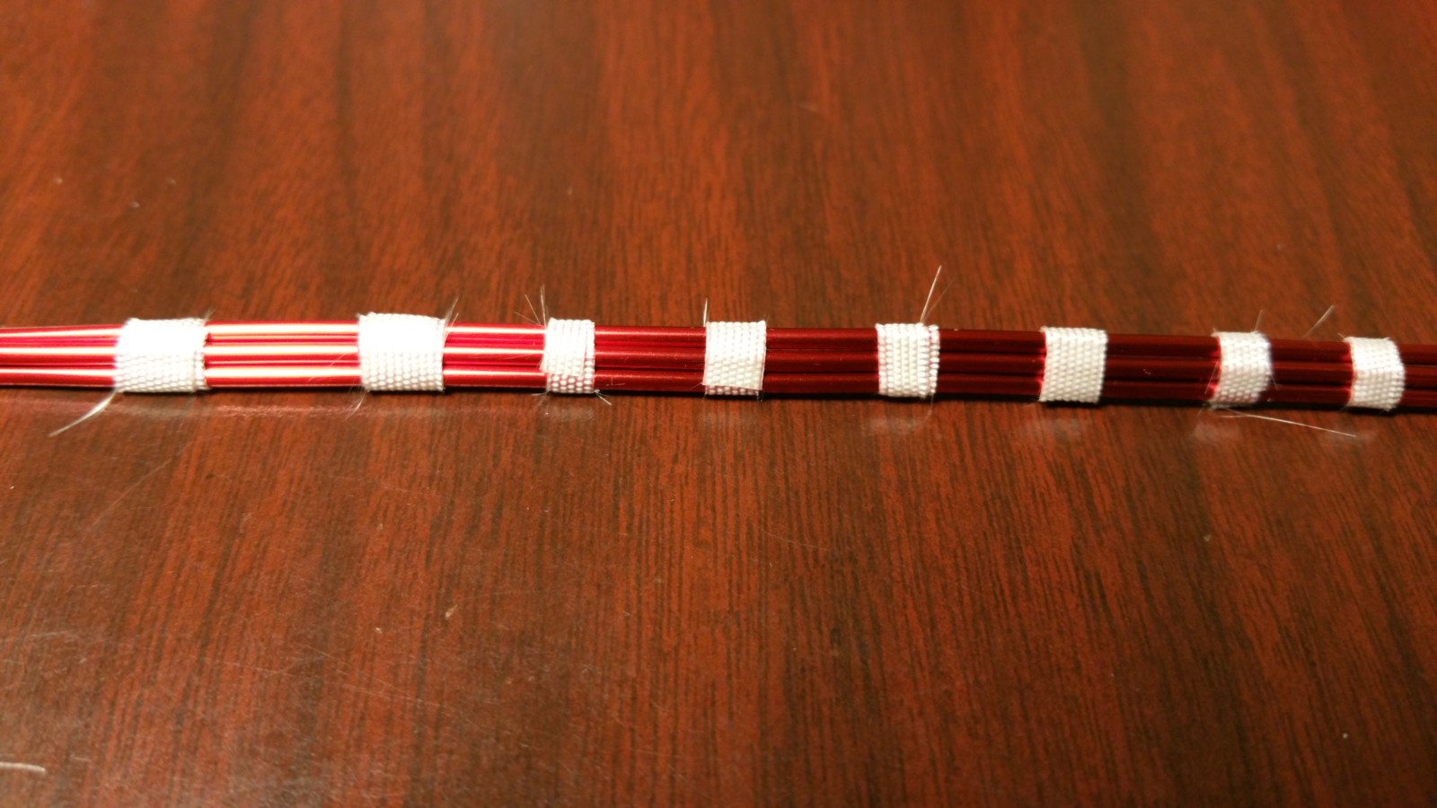
Next, I cut small strips of the fiberglass tape shown above to make the transmission line as shown below. The tape has a silicone adhesive, is rated to over 500 degrees F, and most importantly it doesn’t stretch. Taping the wires like this makes it much easier to wind the toroid core while keeping the conductors side-by-side.
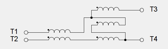
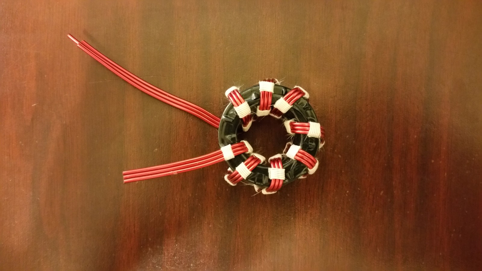
Below is the finished toroid with eight trifilar turns. These will be wired in series and used like an autotransformer with a 1.5 to 1 turns ratio, giving a 2.25 to 1 impedance transformation. In other words, this configuration is a 2.25 to 1 unun, transforming 50 ohms to 112.5 ohms.
Next we use an FT240-43 toroid and a two conductor transmission line made from 14 AWG magnet wire to make the isolator or 1:1 balun. The objective here is to come up with the highest common mode impedance using the least amount of wire. I chose type 43 material which is cheaper, has much higher permeability, and higher loss, for the following reasons:
- We want to minimize inter-turn capacitance in order to keep the self-resonant frequency of the balun as high as possible. That means we want as few turns as possible. Type 61 material has a permeability of 125. Permeability of type 43 is 850, allowing fewer turns to reach a certain inductance.
- Type 43 material has higher loss but in this application it doesn’t matter — it’s actually a benefit. Core magnetization in this type of 1:1 balun is theoretically zero. If there’s no core magnetization then there’s no loss. The only core magnetization that might occur results from the small common mode currents that we’re trying to get rid of. If those disappear as heat in the core, so much the better. Core heating in this kind of balun only becomes significant at power levels well beyond 1500 watts so it can be ignored.
- Type 43 material costs much less than 61, which is nice, but didn’t drive the choice.
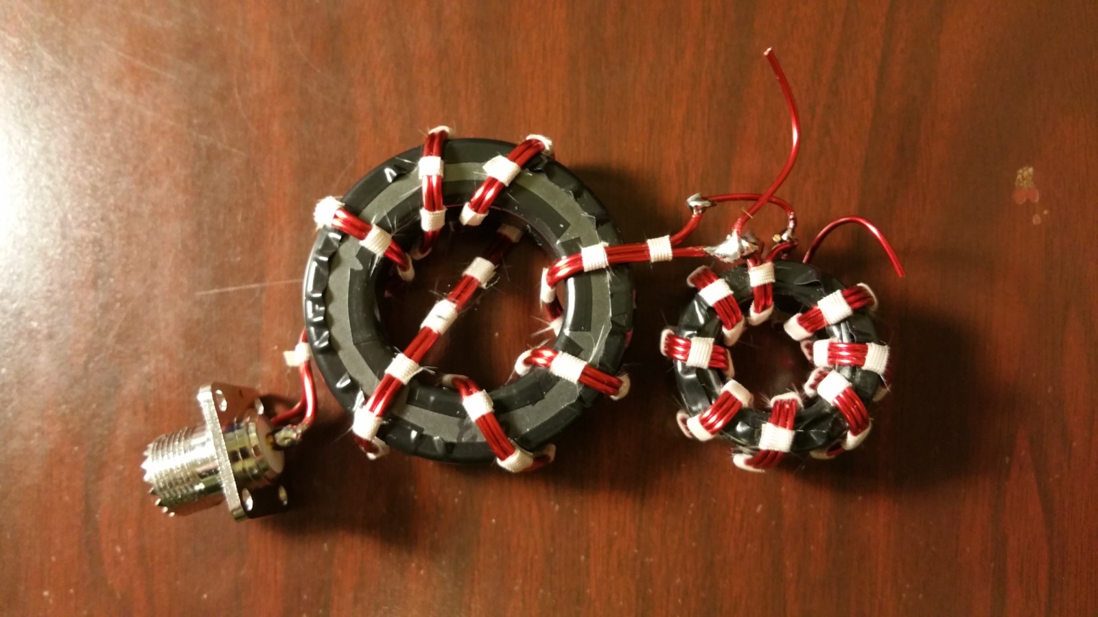
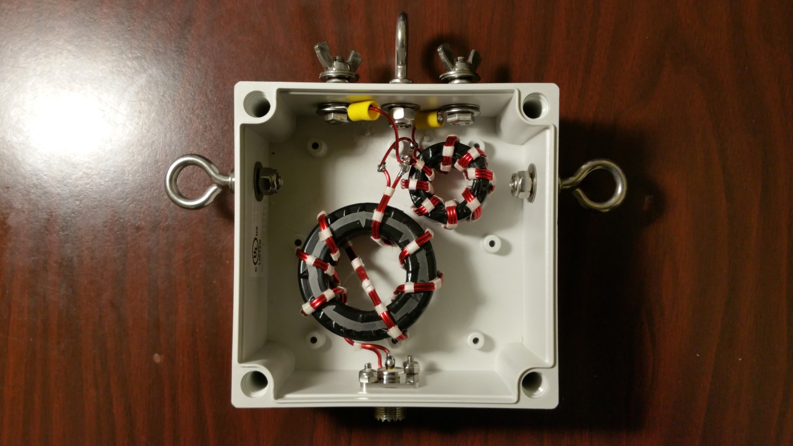
Below is the finished isolator with six turns, connected to the 2.25:1 unun, ready to be installed in an outdoor rated housing. Note the crossover. The crossover has no effect on the performance of the transformer and provides for the input and output wires to come out on opposite sides, which is handy in this case.
Below are the two transmission line transformers installed in a Bud NEMA4 waterproof polycarbonate box. All hardware is 18-8 stainless.
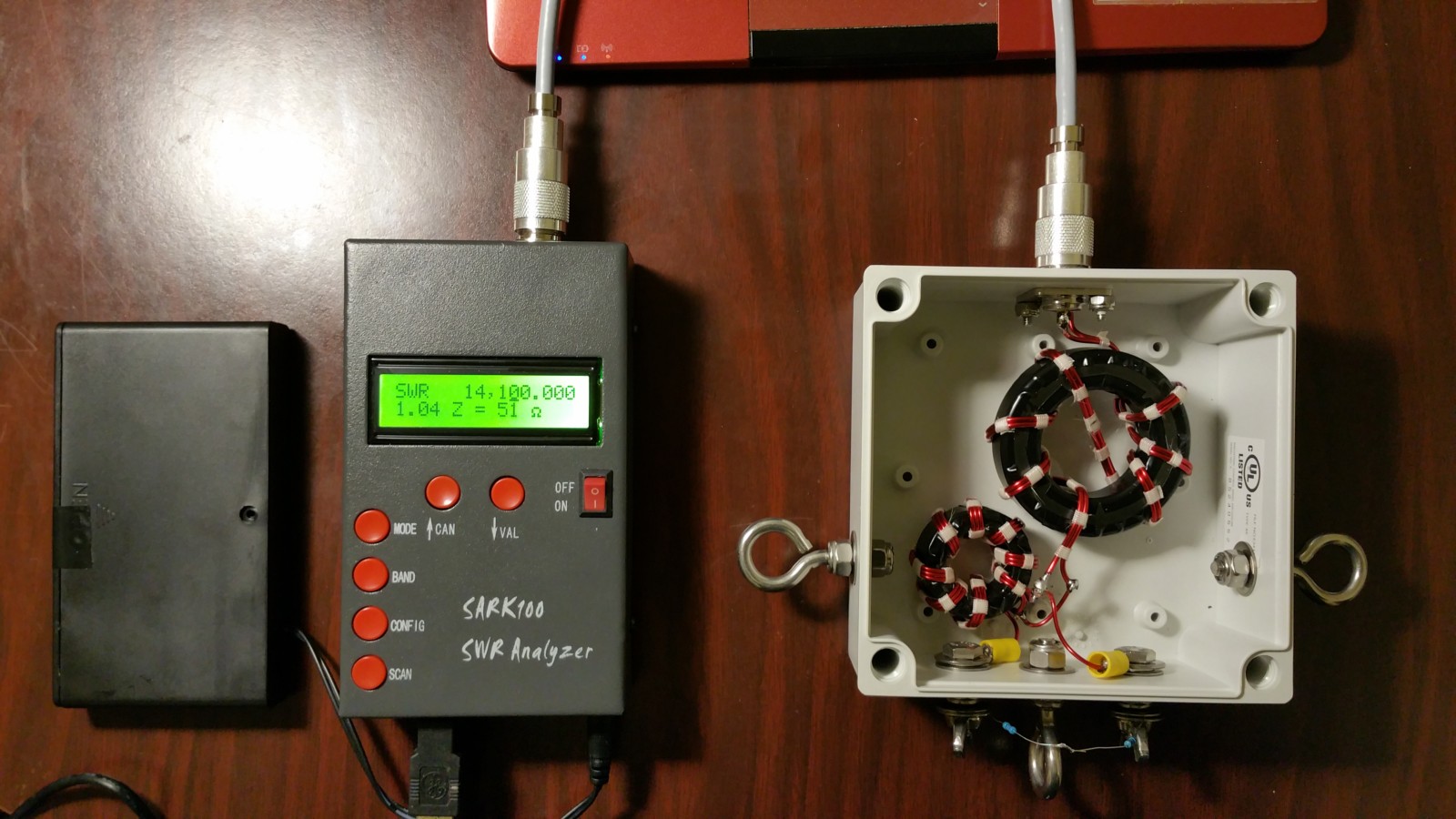
Shown below is the first test setup. A 115 ohm 1% resistor is fixed across the balanced output terminals and the analyzer was swept, taking 500 samples from 3 to 30 MHz. SWR measured nearly flat with 1.01 at 3 MHz, rising to 1.09 at 30 MHz. The photo shows the analyzer at 14.1 MHz reading 51 ohms, exactly what one would expect with 115 ohms on the output terminals.
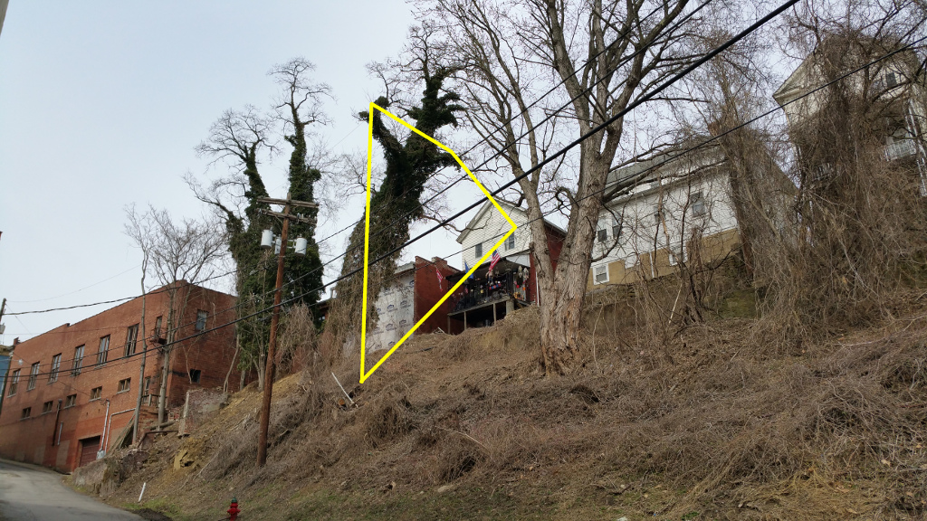
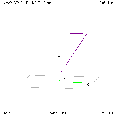
Below is a 500 sample sweep from 3 to 30 MHz of the final installation. I originally made the antenna using 143 feet of wire, which in my experience is a little long so I can trim it. Because this installation has one leg of the triangle parallel to and 10 feet off the slope of the hill behind my house. The antenna resonated about 3 percent low. My calculation said to shorten it by 5 feet, which brought the antenna to exactly where I want it.
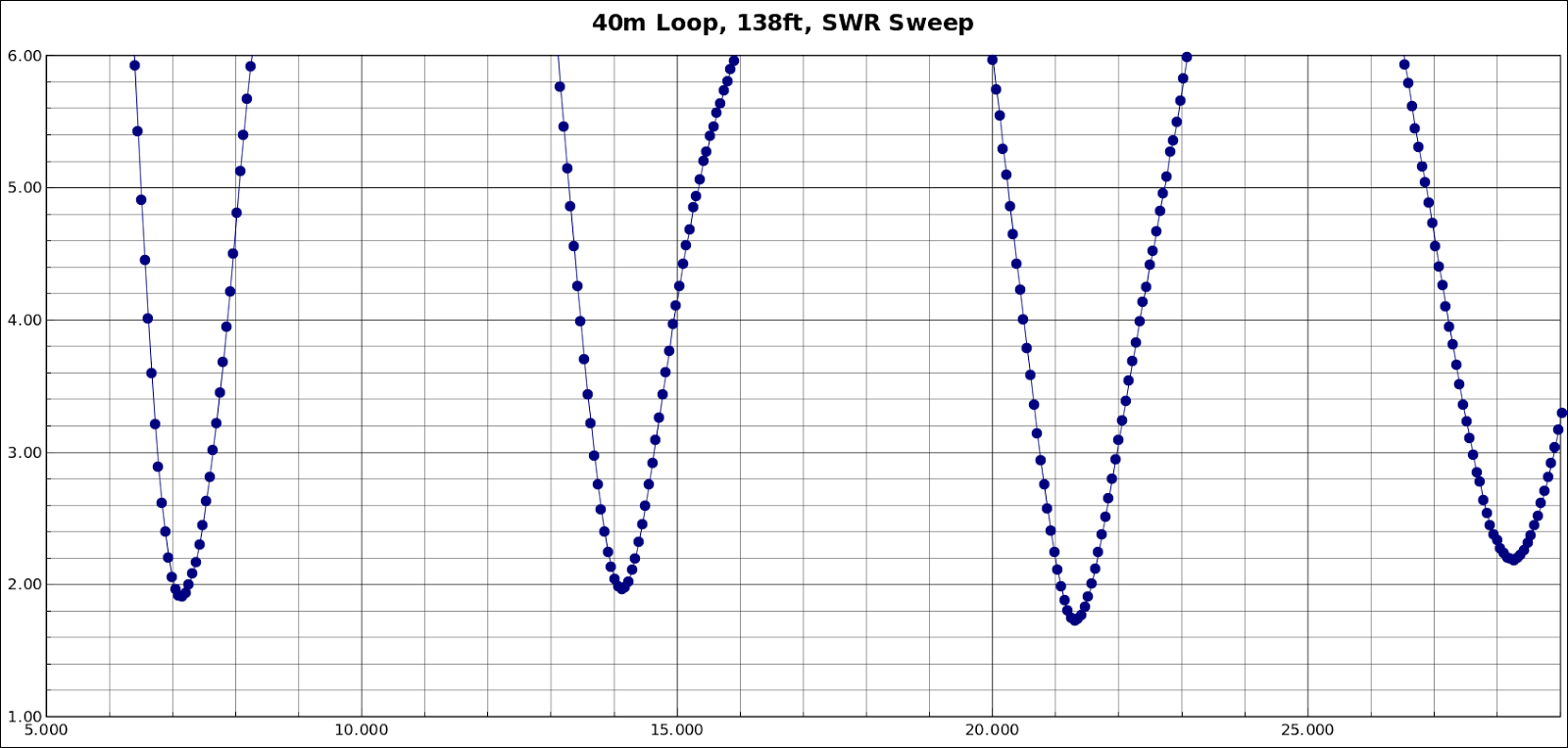
The antenna can be used on all four bands without a tuner.
Look for me at night around 7070 kHz on PSK31, Contestia, Olivia, Thor, PSK63F, and Hellschreiber modes. 73 de KW2P.
Recent Comments